

Vehicle control system for minimizing fuel consumption
a technology of vehicle control system and fuel consumption, applied in the field of vehicle control system, can solve the problems of increased braking distance, increased fuel consumption, increased fuel consumption, etc., and achieve the effect of reducing the fuel consumption amount of the driving source and increasing the accuracy of minimizing the fuel consumption amoun
- Summary
- Abstract
- Description
- Claims
- Application Information
AI Technical Summary
Benefits of technology
Problems solved by technology
Method used
Image

Examples
first embodiment
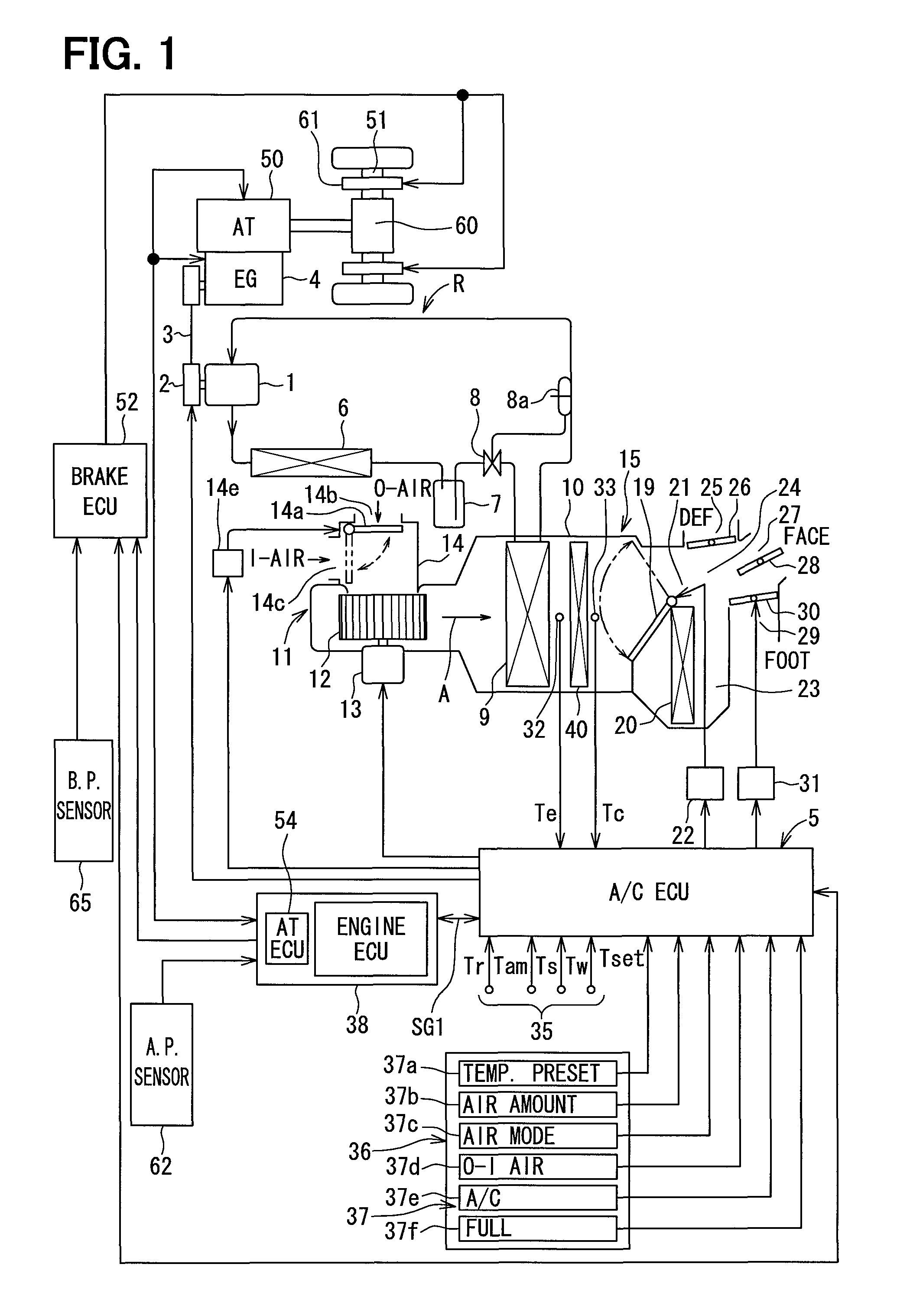
[0140]A first embodiment of the present disclosure will be explained with reference to FIGS. 1 to 8. FIG. 1 shows a system structure for a vehicle control system according to a first embodiment of the present disclosure, including an air-conditioning apparatus and a brake control apparatus for a vehicle. In the present embodiment, a cool-storage device 40 is provided in the air-conditioning apparatus 15 (hereinafter, A / C apparatus 15), a refrigerating cycle R of which is operated by a variable-capacity type compressor 1. A continuously variable transmission (CVT) apparatus is used as a transmission apparatus 50.
[0141]The A / C apparatus 15 for a vehicle will be explained at first. The compressor 1 is provided in the refrigerating cycle R for withdrawing, compressing and discharging refrigerant. The compressor 1 is of the variable-capacity type, so that flow amount of the refrigerant is continuously controlled in accordance with control current from an air-conditioner control unit 5 (h...
second embodiment
[0273]A second embodiment of the present disclosure will be explained.
[0274]In the first embodiment, the cool-storage device 40 is cooled down by the cold air passing through the evaporator 9. However, the cool-storage device 40 may be provided in the refrigerating cycle, for example, as disclosed in Japanese Patent Publication No. 2009-12721. FIG. 9 is a system structure showing the A / C apparatus 15 for the vehicle according to the second embodiment.
[0275]In FIG. 9, the refrigerating cycle R is composed of the compressor 1, the condenser 6, the receiver 7, the expansion valve 8, the heat-exchanger 9 provided in the passenger compartment (that is, the evaporator 9) and the cool-storage device 40, which are connected in series to each other by refrigerant pipes (indicated by lines) to form the closed circuit. The refrigerant flows in the closed circuit.
[0276]As shown in FIG. 9, the cool-storage device 40 having the cool-storage material 44 is provided in the refrigerant cycle R, thro...
third embodiment
[0279]A third embodiment of the present disclosure will be explained. In the first embodiment, the four compressor-control patterns are provided (FIG. 5) in view of not increasing the computing load for the A / C ECU. However, the number of the compressor-control patterns can be increased when high-speed processing is possible in the A / C ECU.
[0280]FIG. 10 is a graph showing compressor-control patterns according to the third embodiment. As shown in FIG. 10, a delay time “TL” is provided for carrying out the compressor-control patterns 31 to 33 and 35. The delay time “TL” can be changed depending on the rotational speed of the compressor 1 (that is, the rotational speed of the engine 4). As shown in FIG. 10, the compressor-control pattern 35 is provided, wherein the pattern 35 has a sharp inclination for increasing the discharging amount of the compressor 1. The pattern 34 shows that the operation of the compressor 1 is stopped.
PUM
 Abstract
Description
Claims
Application Information