
Seat belt retractor and seat belt apparatus including the same

a seat belt and retractor technology, applied in the direction of safety belts, pedestrian/occupant safety arrangements, vehicular safety arrangements, etc., can solve the problems of internal teeth not being able to satisfactorily mesh with external teeth, difficult to effectively prevent the withdrawal of seat belts, and internal teeth sliding over (or skipping) internal teeth, etc., to achieve enhance the effect of meshing and simple movement of the spool

Inactive Publication Date: 2015-02-10
JOYSON SAFETY SYST JAPAN KK
View PDF34 Cites 2 Cited by
  • Summary
  • Abstract
  • Description
  • Claims
  • Application Information

AI Technical Summary

Benefits of technology

[0009]In view of the above, the present invention is to provide a seat belt retractor that is capable of realizing more effective meshing between a plurality of internal teeth and external teeth corresponding thereto, and to provide a seat belt apparatus including the same.
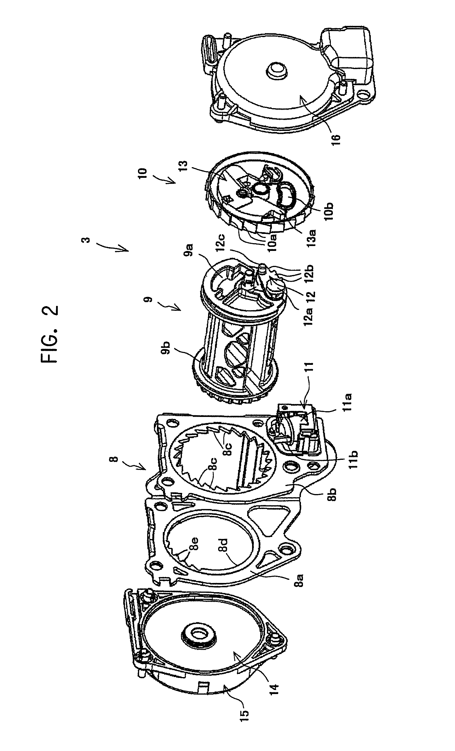
[0015]In the seat belt retractor according to the present invention configured as described above, the second sidewall has a circular hole and the circular hole has on the inner circumferential surface thereof the second internal teeth. The second external teeth of the spool fit with play in the circular hole and some of the second external teeth are meshable with the respective second internal teeth by the other end side of the spool that is moved in the direction of seatbelt load with the load acting on the seat belt. In the case of an emergency, the first engaging portion at the one side end of the spool is made to engage with the first internal teeth provided on the first sidewall of the frame, and the other side end of the spool is moved in the direction of seat belt load with the load acting on the seat belt, whereby the other side end of the spool is brought into contact with the spool pushing portion that is provided on the inner circumferential surface of the second sidewall. Since the other side end of the spool tends to move further in the direction of seat belt load with the load acting on the seat belt, the spool pushing portion pushes the other side end of the spool and brings some of the second external teeth into contact with the second internal teeth of the frame, causing the second external teeth to fit deeply into gaps between adjacent ones of the second internal teeth. Hence, meshing between some of the second external teeth of the spool that face the second internal teeth of the frame and the respective second internal teeth can be realized more effectively.
[0016]In this case, only the other side end of the spool is moved while being pushed by the spool pushing portion. Therefore, some of the second external teeth of the spool can be made to mesh with the respective second internal teeth of the frame more effectively with a simple movement of the spool.
[0017]Furthermore, the toggle effect enhances the meshing between some of the second external teeth and the second internal teeth. Hence, the second external teeth of the spool can be made to mesh with the respective second internal teeth of the frame much more effectively.
[0018]In the seat belt apparatus including the seat belt retractor according to the present invention, some of the second external teeth provided at the other side end of the spool and the second internal teeth of the frame can be made to mesh with each other more effectively with a simple movement of the spool. Therefore, in the case of the emergency described above, the occupant can be restrained by the seat belt more effectively.

Problems solved by technology

However, when the internal teeth start to mesh with the external teeth, the external teeth may slide over (or skip) the internal teeth because of the large load applied to the spool via the seat belt.
Accordingly, the internal teeth may not satisfactorily mesh with the external teeth, making it difficult to effectively prevent the withdrawal of the seat belt in the case of the emergency described above.

Method used


Image

  • Seat belt retractor and seat belt apparatus including the same
  • Seat belt retractor and seat belt apparatus including the same
  • Seat belt retractor and seat belt apparatus including the same

Examples


Embodiment Construction

[0023]Embodiments of the present invention will now be described with reference to the drawings.

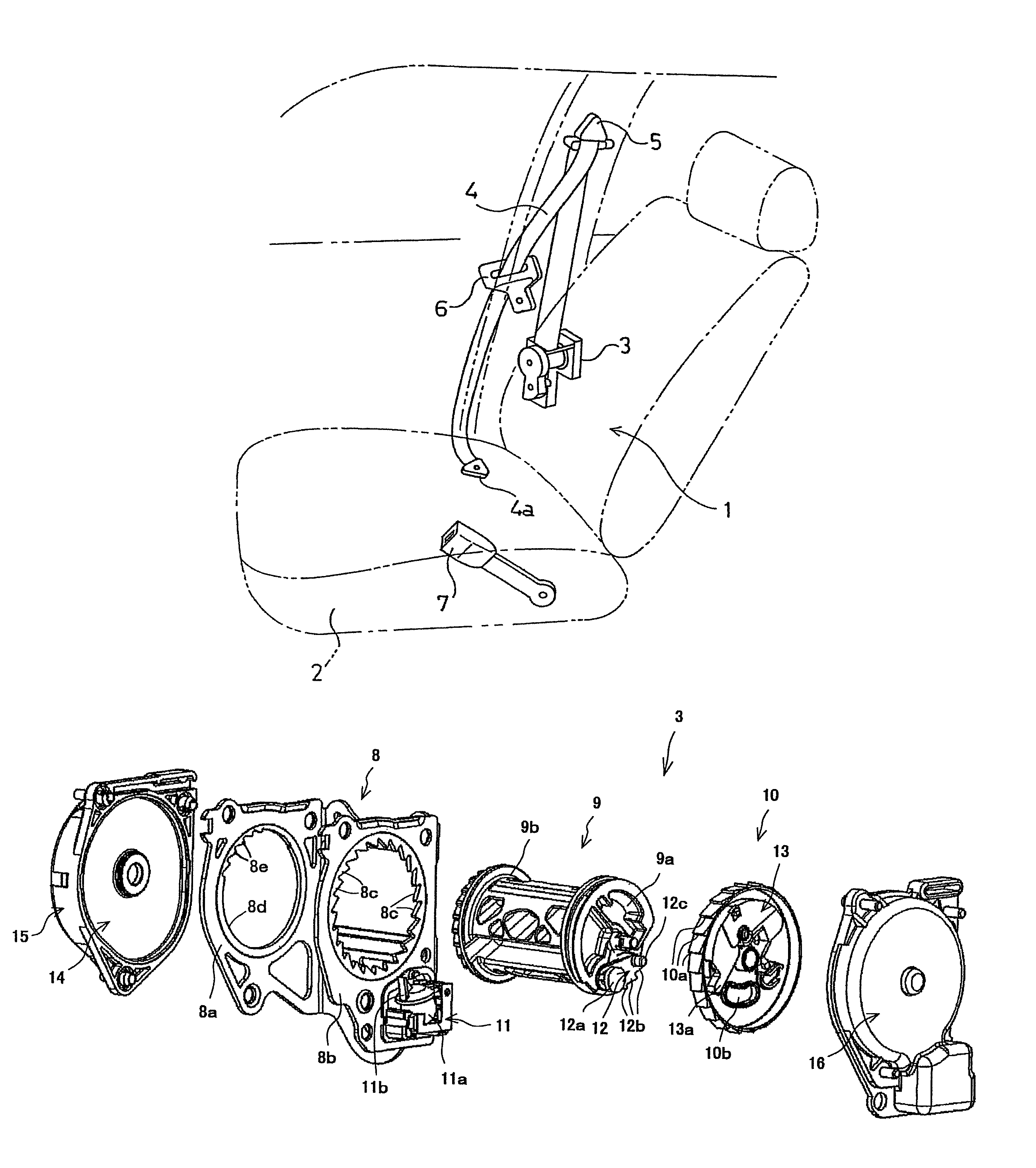
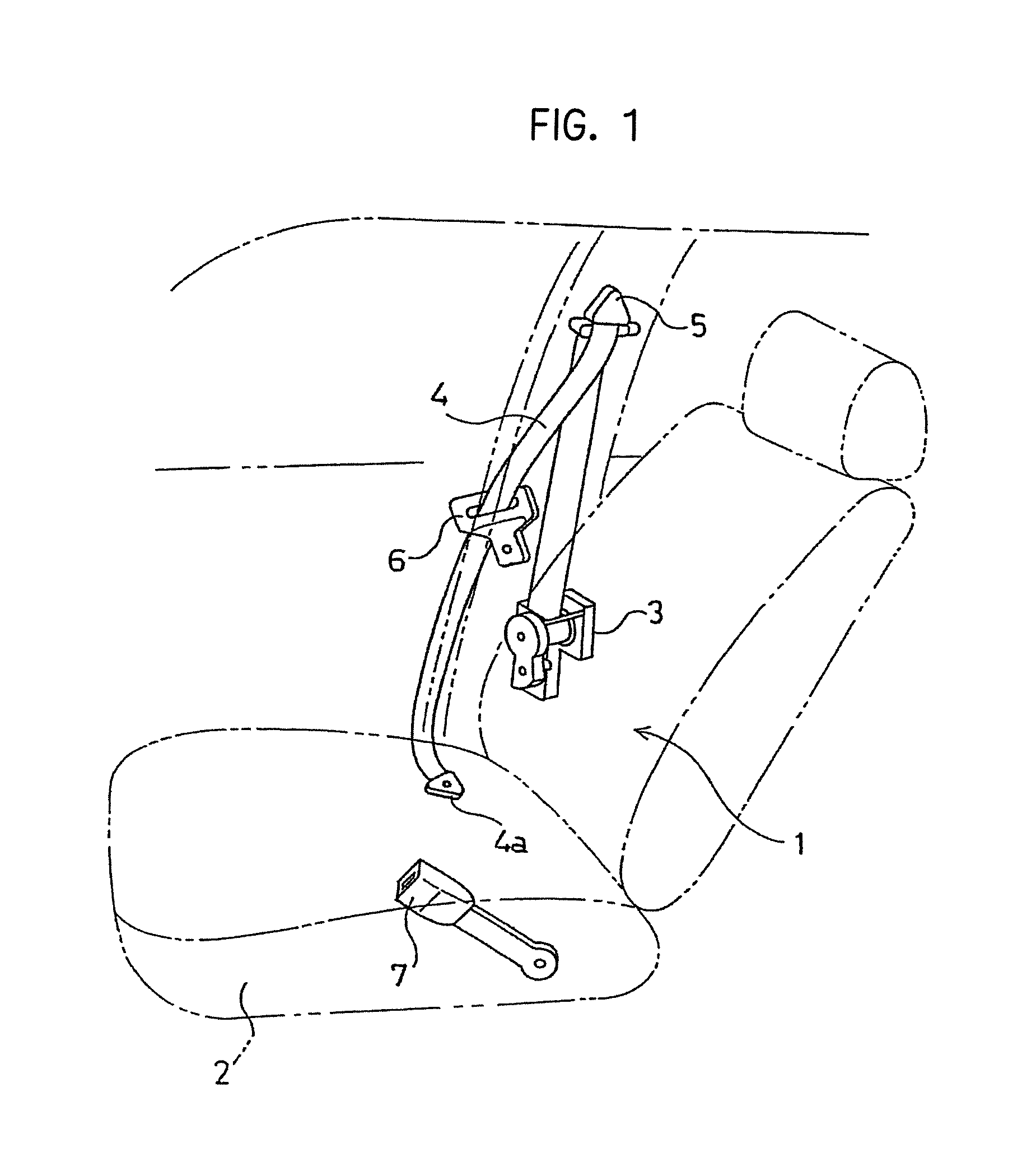
[0024]FIG. 1 is a schematic diagram of a seat belt apparatus including an exemplary embodiment of the seat belt retractor according to the present invention. FIG. 2 is a schematic perspective view of a seat belt retractor according to the embodiment.

[0025]As illustrated in FIG. 1, a seat belt apparatus 1 according to the embodiment is basically the same as a conventionally known three-point seat belt apparatus. Referring to the drawing, reference numeral 1 denotes the seat belt apparatus. Reference numeral 2 denotes a vehicle seat. Reference numeral 3 denotes a seat belt retractor provided near the vehicle seat 2. Reference numeral 4 denotes a seat belt that is to be withdrawably retracted by the seat belt retractor 3 and has a belt anchor 4a provided at the leading end thereof. The belt anchor 4a is configured to be secured to the floor of a vehicle body or to the vehicle seat 2. Referen...


PUM


Abstract

During an emergency, in one form of a retractor having a spool, external teeth of a pawl provided at a spool right side end are made to mesh with some of internal teeth provided on a frame, and, with load acting on a seat belt, a spool left side end is brought into contact with a spool pushing portion. Since the spool left side end tends to be moved further in a direction of seat belt load with the load acting on the seat belt, the spool pushing portion pushes the spool left side end, whereby some of external teeth come into contact with internal teeth provided on the frame and fit deeply into gaps between adjacent ones of the internal teeth. Thus, some of the external teeth of the spool effectively come into mesh with the respective internal teeth of the frame with a simple movement of the spool.

Description

CROSS-REFERENCE TO RELATED APPLICATIONS[0001]This application is a National Phase Patent Application of International Patent Application Number PCT / JP2011 / 003148, filed on Jun. 3, 2011, which claims priority of Japanese Patent Application Number 2010-151269, filed on Jul. 1, 2010, which are hereby incorporated herein by reference in their entirety.FIELD OF THE INVENTION[0002]The present invention relates to a technical field concerning a seat belt retractor that prevents, in the case of an emergency such as at a collision of a vehicle in which a deceleration that is larger than a specific value is experienced by the vehicle, the withdrawal of a seat belt by locking the rotation of a spool around which the seat belt is to be retracted, and also concerning a seat belt apparatus including the same.BACKGROUND OF THE INVENTION[0003]Conventionally, a seat belt apparatus included in a vehicle such as an automobile prevents, in the case of an emergency such as at a collision of the vehicle,...

Claims


Application Information

Patent Timeline
Patent Type & Authority Patents(United States)
IPC IPC(8): A62B35/00A62B35/04B60R22/00B60R22/36B60R22/405
CPCB60R22/36B60R22/405
Inventor YOSHIOKA, HIROKAZUOSADA, KENJISESAKI, TAKASHI
Owner JOYSON SAFETY SYST JAPAN KK
Learn More