

Method of boring work by 5-axis machining double-housing machine tool and 5-axis machining double-housing machine tool
a technology of machining double-housing and workpiece boring, which is applied in the direction of manufacturing tools, driving apparatus, metal-working machine components, etc., can solve the problems of reducing the workpiece's rotation rate, increasing the energy consumption, and limiting the weight of the workpiece, so as to achieve the effect of sacrificing the machining accuracy
- Summary
- Abstract
- Description
- Claims
- Application Information
AI Technical Summary
Benefits of technology
Problems solved by technology
Method used
Image

Examples
Embodiment Construction
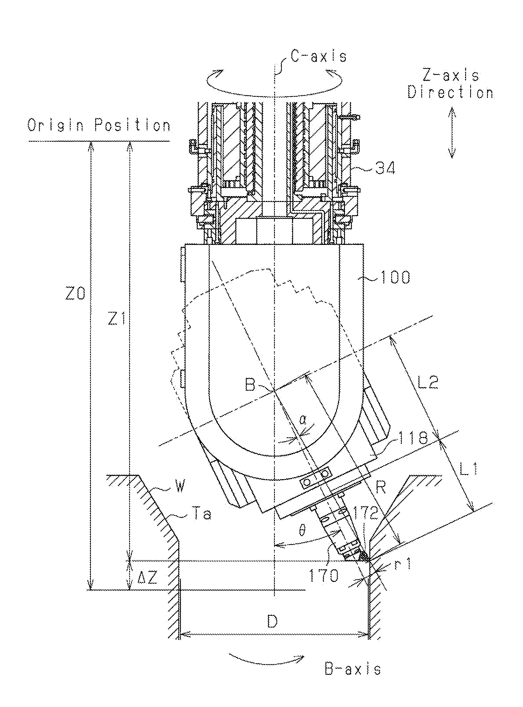
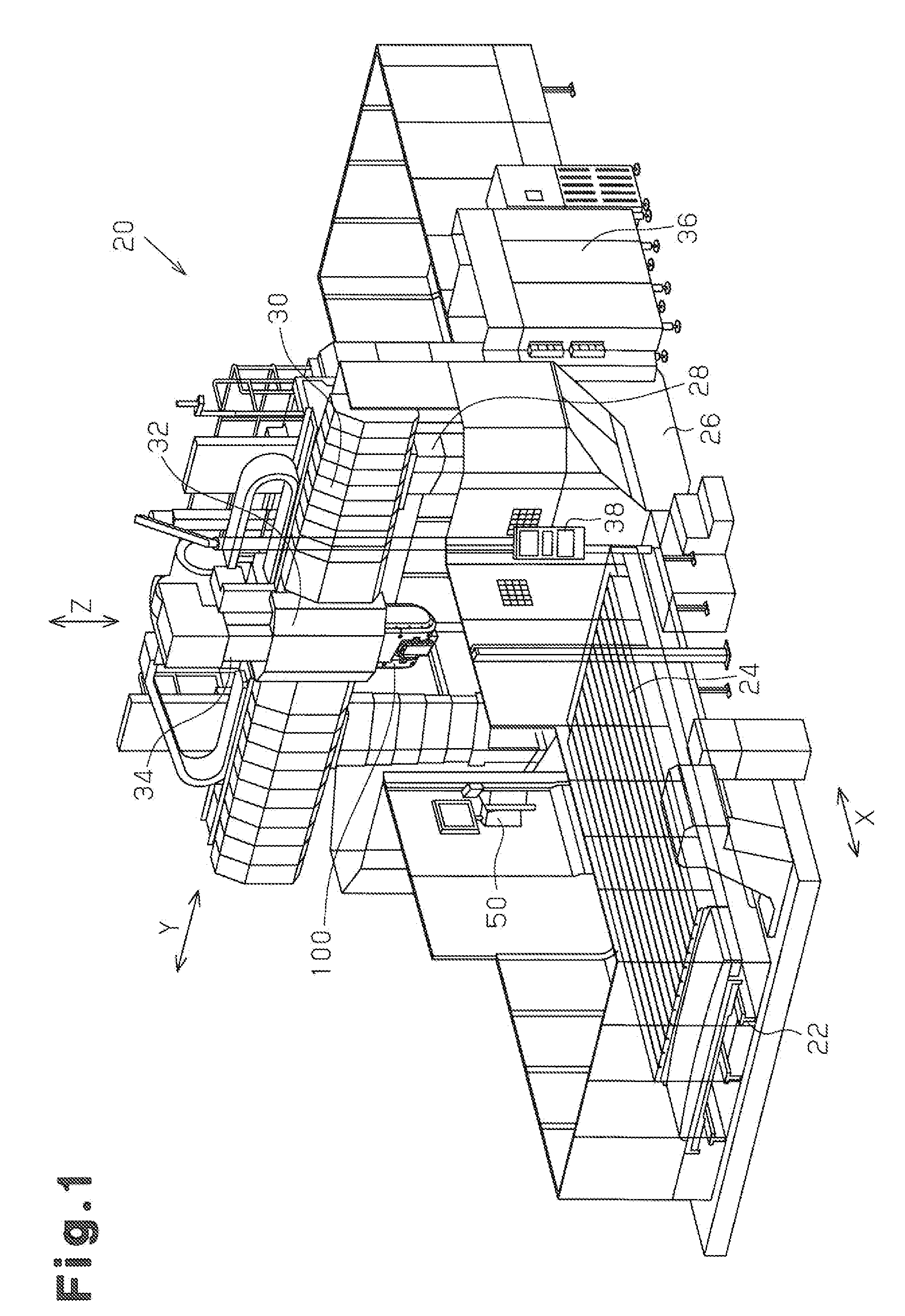
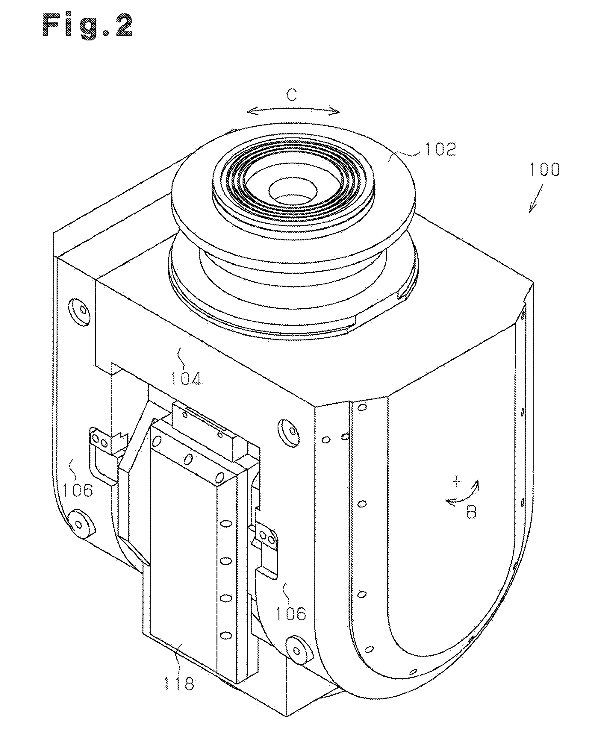
[0040]A 5-axis machining double-housing machine tool according to the present invention, which is a machining center 20 according to one embodiment, will now be described with reference to FIGS. 1 to 7.
[0041]As shown in FIG. 1, the machining center 20 includes a table24 arranged on a base 22. The table 24 is actuated by an X-axis drive motor Mx shown in FIG. 7, so as to move along an X-axis, which is the lateral and longitudinal direction of the table 24, with a workpiece W mounted thereon.
[0042]A double-housing column 28 extends upward from a column base 26. The column 28 has a cross rail 30. The cross rail 30 is guided by the column 28, and actuated by a W-axis drive motor Mw shown in FIG. 7, so as to move upward and downward along a W-axis, which is the same direction as a Z-axis direction extending vertically. A saddle 32 is arranged on the cross rail 30. The saddle 32 is movable along a Y-axis, which extends horizontally, by a ball screw (not shown) actuated by a Y-axis drive m...
PUM
| Property | Measurement | Unit |
|---|---|---|
| weight | aaaaa | aaaaa |
| diameter | aaaaa | aaaaa |
| diameter | aaaaa | aaaaa |
Abstract
Description
Claims
Application Information