
Communications system

a communication system and communication technology, applied in the field of mobile telecommunication networks, can solve the problems of mobile devices being used to “ping-pong” and cell full utilization, and achieve the effects of reducing repeated handover, reducing repeated handover, and reducing repeated handover

Active Publication Date: 2015-02-10
NEC CORP
View PDF8 Cites 13 Cited by
  • Summary
  • Abstract
  • Description
  • Claims
  • Application Information

AI Technical Summary

Benefits of technology

The present invention provides techniques for controlling handover and cell reselection parameters used by different RATs to efficiently load balance mobile devices. This is achieved by generating a message for a neighboring cell of a different RAT, the message including information for use in determining new handover and cell reselection parameters for the neighboring cell. The message is sent to the cell of the other RAT. The invention also includes a mobile communications device that makes signal measurements in accordance with the handover and cell reselection parameters broadcast by a serving cell, and a non-E-UTRAN communications system that receives the message and transmits the new cell selection parameters into the non-E-UTRAN cell. The technical effects of the invention include reducing repeated handover and cell reselection of mobile devices between different RATs, improving network load balancing, and improving user experience.

Problems solved by technology

A problem with these handover and cell reselection processes is that they can lead to some cells being fully utilised whilst other cells are underutilised.
The inventors have realised, however, that if the mobile device moves to a cell of a different Radio Access Technology (RAT), the handover and cell reselection parameters of the new cell may cause the mobile device to select the E-UTRAN cell again, thereby causing the mobile device to “ping-pong” between the E-UTRAN cell and the other cell.

Method used


Image

  • Communications system
  • Communications system
  • Communications system

Examples


Embodiment Construction

Overview

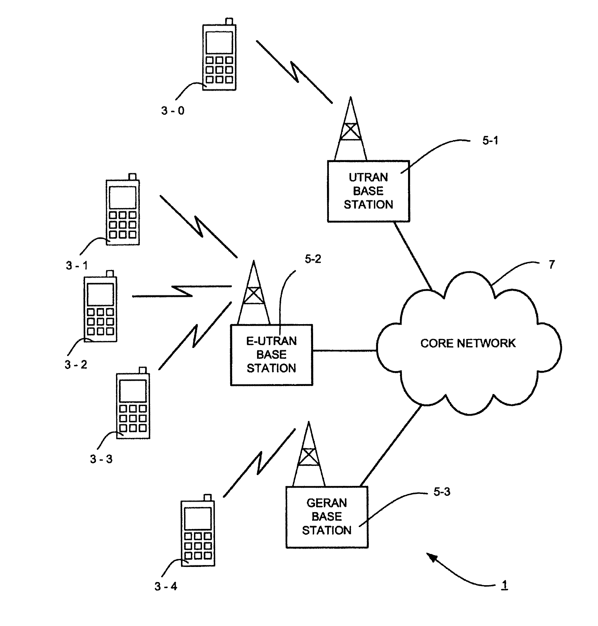
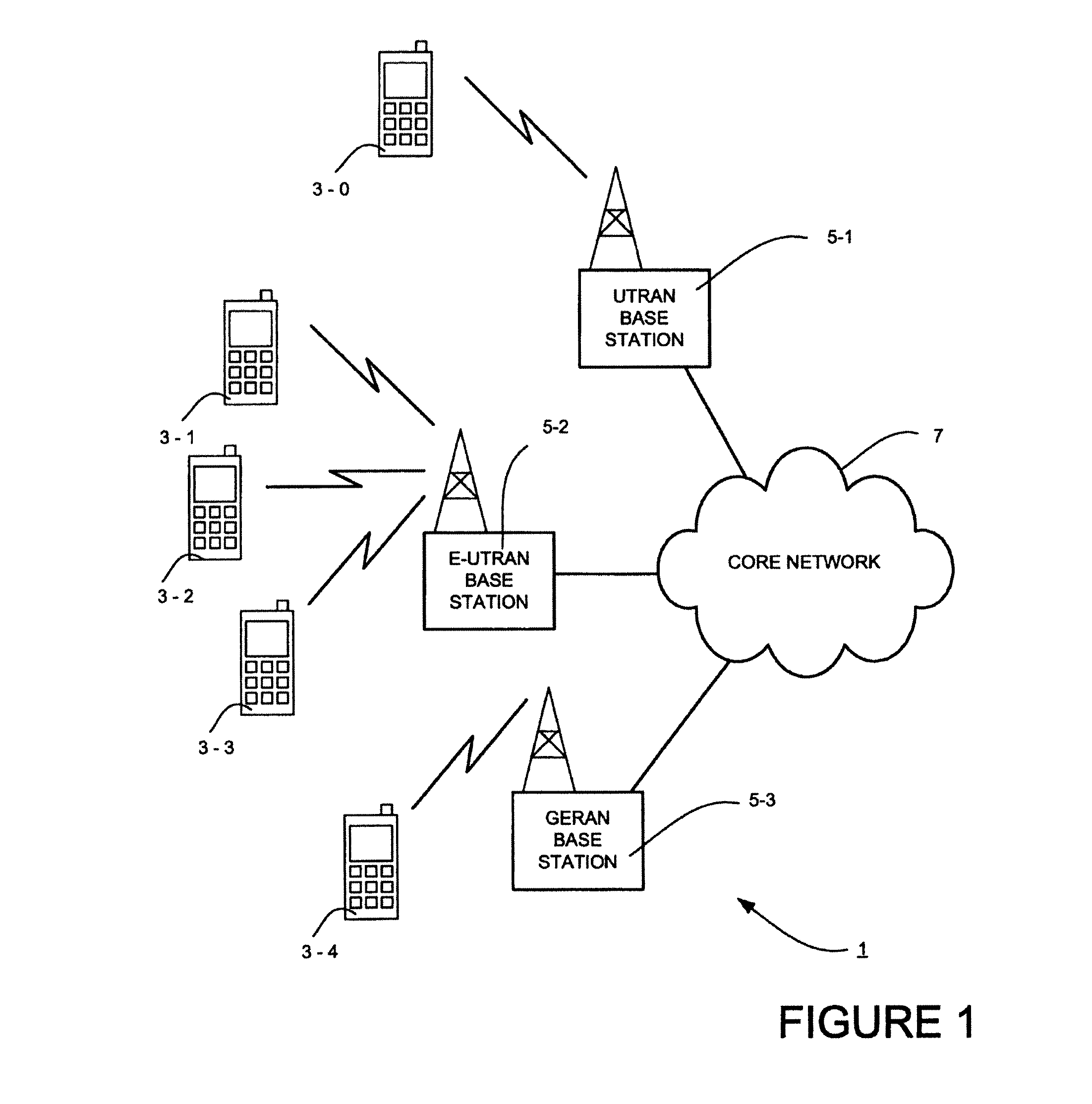
[0021]FIG. 1 schematically illustrates a mobile (cellular) telecommunication system 1 in which users of mobile telephones 3-0, 3-1, 3-2, 3-3 and 3-4 can communicate with other users (not shown) via one of the base stations 5-1, 5-2 or 5-3 and a telephone core network 7. In the system illustrated in FIG. 1, the base station 5-1 is a UTRAN base station and it is currently serving mobile telephone 3-0; base station 5-2 is an E-UTRAN base station and it is currently serving mobile telephones 3-1, 3-2 and 3-3; and base station 5-3 is a GERAN base station and it is currently serving mobile telephone 3-4. Each base station 5 operates a number of base station cells, each having a number of uplink and downlink communications resources (sub-carriers, time slots etc) that are available for wireless communication between the mobile telephones 3 and the corresponding base station 5. In this embodiment, it will be assumed for the sake of simplicity of explanation, that each base station 5...


PUM

PropertyMeasurementUnit
thresholdaaaaaaaaaa
areaaaaaaaaaaa
signal strengthaaaaaaaaaa

Abstract

A mobile communications system is described in which an E-UTRAN base station dynamically changes its handover and / or its cell reselection parameters to control the load on the base station and which transmits a message to a non E-UTRAN neighboring cell, so that it can adapt its handover and / or its cell reselection parameters to avoid repeated handover and / or cell reselection of a mobile communications device between the non E-UTRAN cell and the E-UTRAN cell.

Description

FIELD OF THE INVENTION[0001]The present invention relates to mobile telecommunication networks, particularly but not exclusively networks operating according to the 3GPP standards or equivalents or derivatives thereof. The invention has particular although not exclusive relevance to the Long Term Evolution (LTE) of UTRAN (called Evolved Universal Terrestrial Radio Access Network (E-UTRAN)) and its interaction with other networks such as UTRAN and GERAN (GSM EDGE Radio Access Network) networks.BACKGROUND ART[0002]In a cellular communications network, mobile devices or User Equipment (UE) roam from cell to cell as the user moves within the area covered by the cellular network. Generally, this roaming is governed by two processes—“handover” when the mobile device is in an active connected mode such as when the mobile device is in a call with another device; and “reselection” when the mobile device is in an idle mode or in a connected mode that does not have dedicated resources. In orde...

Claims


Application Information

Patent Timeline
Patent Type & Authority Patents(United States)
IPC IPC(8): H04W36/00C07K14/195C12N15/82H04W36/14H04W36/22
CPCH04W36/0094C07K14/195C12N15/8271C12N15/8273H04W36/14H04W36/22H04W36/00837H04W36/24H04W36/304H04W36/1443H04W36/26H04W36/38H04W36/0061H04W28/09
Inventor PATERSON, ROBERT
Owner NEC CORP
Learn More