
Vital information measuring device

a technology of vital information and measuring device, which is applied in the field of vital information measuring device, can solve the problems of inability to obtain accurate measurement data, inability to sleep well, and discomfort of subjects, and achieve the effect of enhancing operability and no or less stress on subjects involved

Active Publication Date: 2015-02-17
KONICA MINOLTA SENSING INC
View PDF32 Cites 11 Cited by
  • Summary
  • Abstract
  • Description
  • Claims
  • Application Information

AI Technical Summary

Benefits of technology

The present invention aims to provide a vital information measuring device that can measure vital information for a long time without causing stress to the person wearing it and enhance its operability.

Problems solved by technology

However, if the cable gets hung up in a bedding item or the like, the sensor device may be detached from the attached site of the subject.
Also, the subject may feel discomfort or stress because the measuring device is attached to the subject's body, with the cable entangled.
Particularly, since the PSG has a large number of sensor devices, the subject may even feel difficulty in rolling over in his or her sleep, which may inhibit good sleep, and resultantly fail to obtain accurate measurement data.
The same drawback is involved in the former conventional arrangement i.e. the disposable pulse oximeter, because the flexible substrate for mounting the sensor device thereon, and the oximeter main body are connected by the cable.
However, the holter monitor and the cordless vital information measuring device have drawbacks that the subject has to carry the receiver for wirelessly receiving a detection signal from the electrodes, and to carry the controller for wirelessly receiving the vital information detected by the sensor, respectively.
In both of the cases, despite the cordless arrangement, the subject may feel stress resulting from carrying some parts of the measuring device.
Also, these arrangements essentially fail to solve the inconvenience due to the fact that the sensor device and the device main body are provided independently of each other.

Method used


Image

  • Vital information measuring device
  • Vital information measuring device
  • Vital information measuring device

Examples


first embodiment

[0068]FIGS. 4A and 4B are diagrams showing a vital information measuring device “S1”, using the flexible substrate 11, according to the invention. FIG. 4A is a front view, and FIG. 4B is a side view. The vital information measuring device “S1” includes the flexible substrate 11, and an outer member 21 which is so designed as to cover the front surface 11a of the flexible substrate 11.

[0069]The outer member 21 has a flexibility, is made of a resin material or a like material having a light blocking function and a waterproof function, and is formed into a sheet-like shape, with a vertical size in FIGS. 4A and 4B sufficiently larger than the corresponding size of the flexible substrate 11. The vertically long sheet-like shape is advantageous in winding the outer member 21 around a fingertip, like an adhesive tape (see FIG. 6). An adhesive layer 21A having an adhesion to a human skin is formed on one surface of the outer member 21. A window portion 21T is formed near a central part of t...

second embodiment

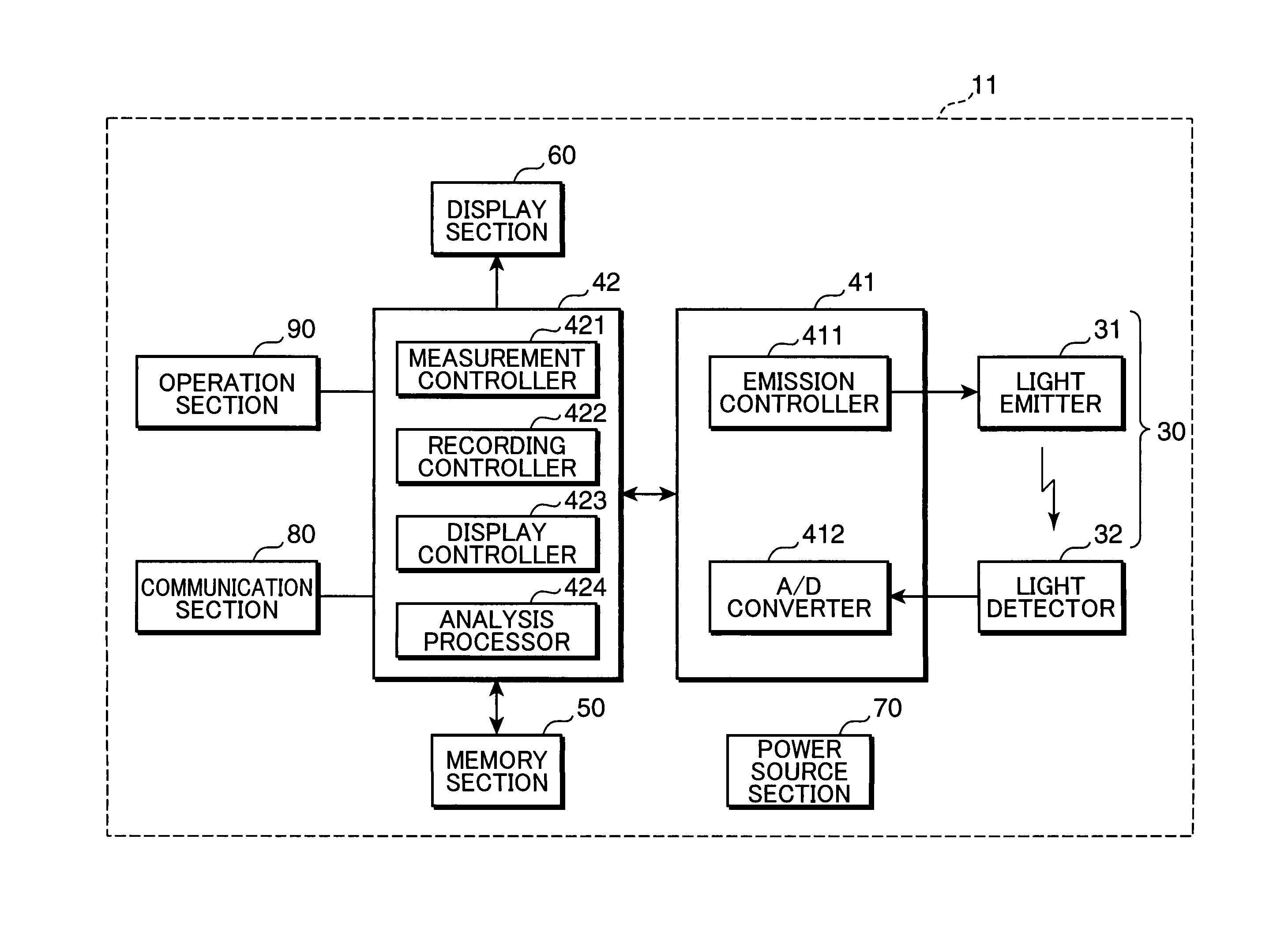
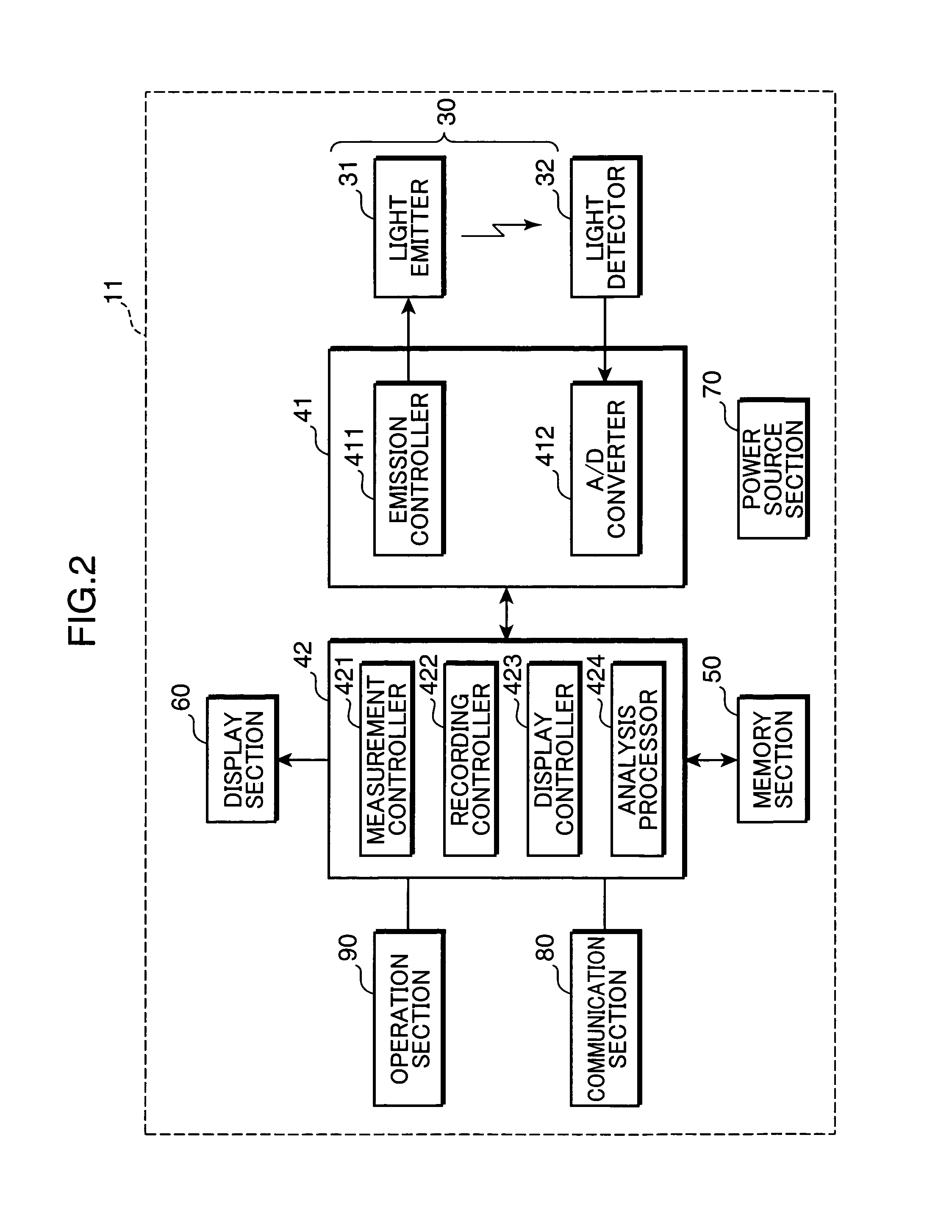
[0074]The flexible substrate 12 includes a rectangular main portion 121, an oblong probe portion 122, and an oblong connecting portion 123. A display section 60 is mounted on a front surface of the main portion 121, and a measurement circuit section 41, a main controller 42, a memory section 50, and a power source section 70 are mounted on a rear surface of the main portion 121. A light emitter 31 and a light detector 32 are mounted on the probe portion 122. The connecting portion 123 is adapted to integrally connecting the main portion 121 to the probe portion 122. As shown in FIG. 7A, the probe portion 122 and the connecting portion 123 extend orthogonal to each other, and are integrally formed into a substantially T-shape. In the second embodiment, the light emitter 31 and the light detector 32 are disposed away from each other, whereby an optical system for transmitting light through a fingertip for measurement is established.

[0075]The outer member 22 includes a rectangular port...

fourth embodiment

[0084]FIGS. 11A and 11B are diagrams showing a vital information measuring device “S4” according to the invention, wherein FIG. 11A is a cross-sectional view, and FIG. 11B is a top plan view. FIG. 12 is a perspective view showing how the vital information measuring device “S4” is removably attached to the finger “f” to be measured. The vital information measuring device “S4” includes a rectangular flexible substrate 14, and a fingerstall-like outer member 24 for housing the flexible substrate 14 therein.


PUM


Abstract

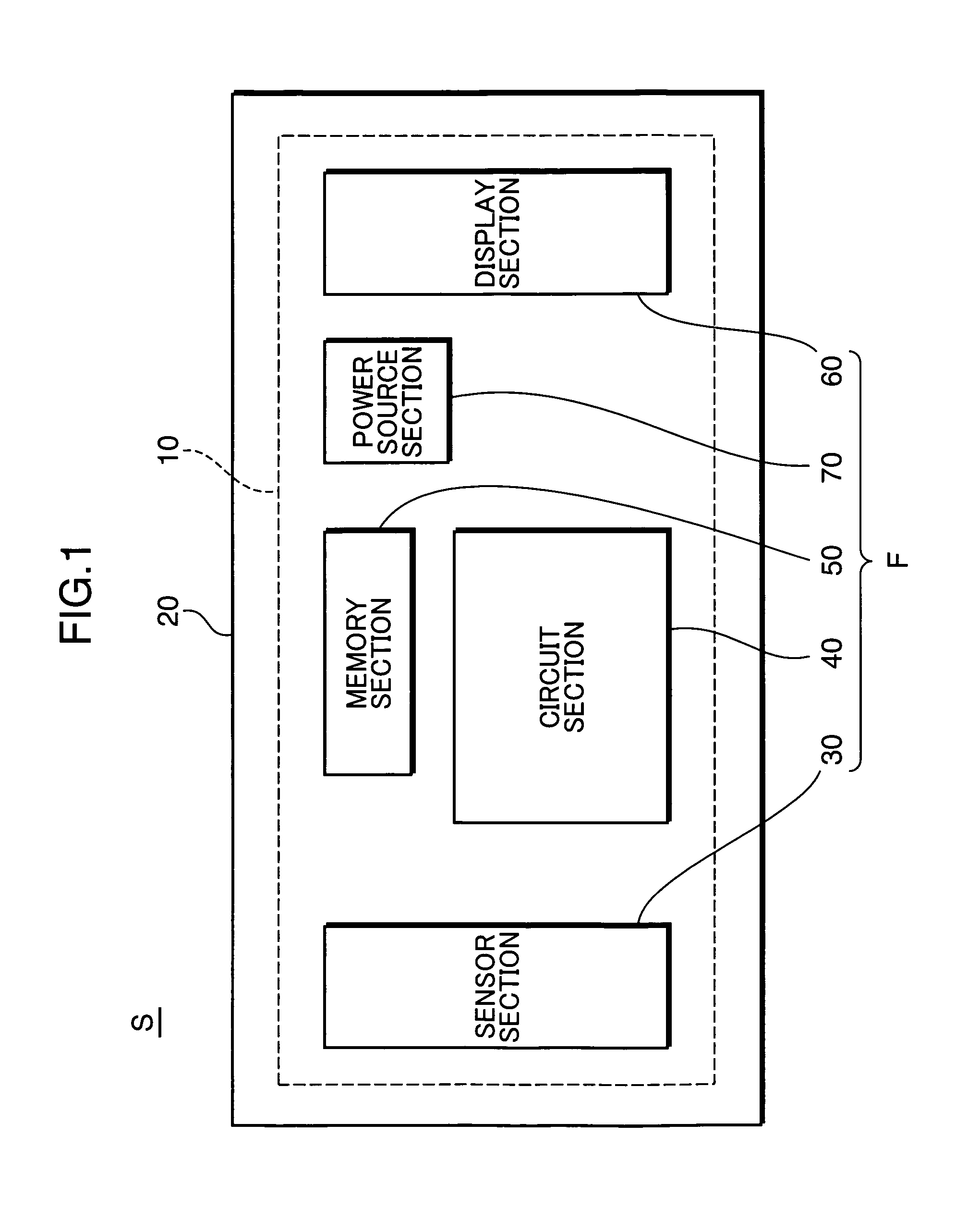
A vital information measuring device includes: a flexible substrate including a functioning part which is mounted thereon; and an outer member for covering the flexible substrate. The functioning part has: a sensor section for sequentially measuring a parameter relating to certain vital information on a subject; a circuit section for performing a predetermined process with respect to a measurement signal outputted from the sensor section; a memory section for storing therein the measurement signal or measurement data after the process by the circuit section; a display section for displaying thereon certain information relating to the measurement; and a power source section for supplying a drive voltage to the respective sections of the functioning part.

Description

[0001]This application is based on Japanese Patent Application No. 2005-300610 filed on Oct. 14, 2005, the contents of which are hereby incorporated by reference.BACKGROUND OF THE INVENTION[0002]1. Field of the Invention[0003]The present invention relates to a vital information measuring device for non-invasively detecting various vital information from a human body, and more particularly to a vital information measuring device adapted to measure vital information for a long time.[0004]2. Description of the Related Art[0005]There are known a pulse oximeter, a PSG (polysomnography), and a holter monitor, as examples of a vital information measuring device for non-invasively detecting vital information from a human body, particularly, as a vital information measuring device requiring a long time vital information detection. As shown in FIG. 25, a pulse oximeter 100 is used in such a manner that: a probe 101 equipped with a light emitter and a light detector is detachably attached to a...

Claims


Application Information

Patent Timeline
Patent Type & Authority Patents(United States)
IPC IPC(8): A61B5/00A61B5/087A61B5/113A61B5/1455A61B5/308A61B8/00
CPCA61B5/6833A61B5/14552A61B5/6826A61B5/6838A61B8/4236A61B5/0002A61B5/0878A61B5/1135A61B2560/0412
Inventor KITAJIMA, KAZUMINAGAI, YOSHIROHISHIKAWA, NORIOYAMAMOTO, KOJI
Owner KONICA MINOLTA SENSING INC
Learn More