Data network with “per flow” flow monitoring

a data network and flow monitoring technology, applied in data switching networks, frequency-division multiplexes, instruments, etc., can solve problems such as afdx to vl routing induced circular dependence, very easily generated problems, etc., to reduce the overall cost of the overall system, simplify the overall cost, and increase the utilization capacity of afdx ethernet topology

Active Publication Date: 2015-02-17
ROCKWELL COLLINS INC
View PDF13 Cites 13 Cited by
  • Summary
  • Abstract
  • Description
  • Claims
  • Application Information

AI Technical Summary

Benefits of technology

[0020]In another broad aspect, the present invention may be embodied as a method for routing data flow in a data network of a type having a plurality of end systems, a plurality of line data buses connected to the end systems, and a plurality of switches connected to the line data buses and to other switches via trunk data buses to define a star topology, the switches and end systems configured to operate asynchronously. Each switch is, configured to operate by the steps of: a) receiving arrival data flows, via a plurality of switch ingress ports each arrival data flow having delay and delay-jitter bound requirements, frame loss probability requirements, and bandwidth provisioning requirements; b) monitoring the arrival data on each flow in defined traffic constraint envelopes containing frames, utilizing a ‘per flow’ flow monitor operatively associated with each flow; c) computing an eligibility time at which arriving frames on each flow will be conformant to the defined traffic constraint envelope given past frame arrivals on that same flow, utilizing an eligibility time computation mechanism; d) holding the arriving frames on each flow until the eligibility time is reached utilizing a holding mechanism; and, e) releasing the arriving frames on a flow at the eligibility time utilizing a release mechanism. The ‘per flow’ flow monitor, the eligibility time computation mechanism, the holding mechanism, and the release mechanism cooperate to provide a ‘per flow’ traffic shaping function in conformance with the delay and delay-jitter bound requirements, the frame loss probability requirements, and the bandwidth provisioning requirements, thus allowing the switch to enforce the traffic constraint envelope for each flow.
[0021]The present invention is particularly advantageous in avionics applications because it increases the utilization capacity of an AFDX Ethernet topology. This could be applicable to future AFDX switch based design approaches. Unlike U.S. Pat. No. 7,675,919, which relates to an end system transmission schedule and U.S. Pat. No. 7,787,486, which relates to establishing coordinated end system transmission schedules for achieving low jitter, the present invention relates to an asynchronous system. This simplifies and reduces the overall cost of the overall system. Unlike U.S. Pat. No. 7,983,195, the present invention does not constrain routing.

Problems solved by technology

However, the ARINC-664 network uses multiple switches and redundant paths to route data, point-to-point or point-to-multipoint across the switches.
This problem is very easily generated in an aircraft as each function is duplicated for availability.
However, it constrains the flow routing making the process more complex.
Second the vulnerability of AFDX to VL routing induced circular dependence.
Third, the introduction of delay-jitter at intermediate AFDX switches in the network.

Method used


Image

  • Data network with “per flow” flow monitoring
  • Data network with “per flow” flow monitoring
  • Data network with “per flow” flow monitoring

Examples


Embodiment Construction

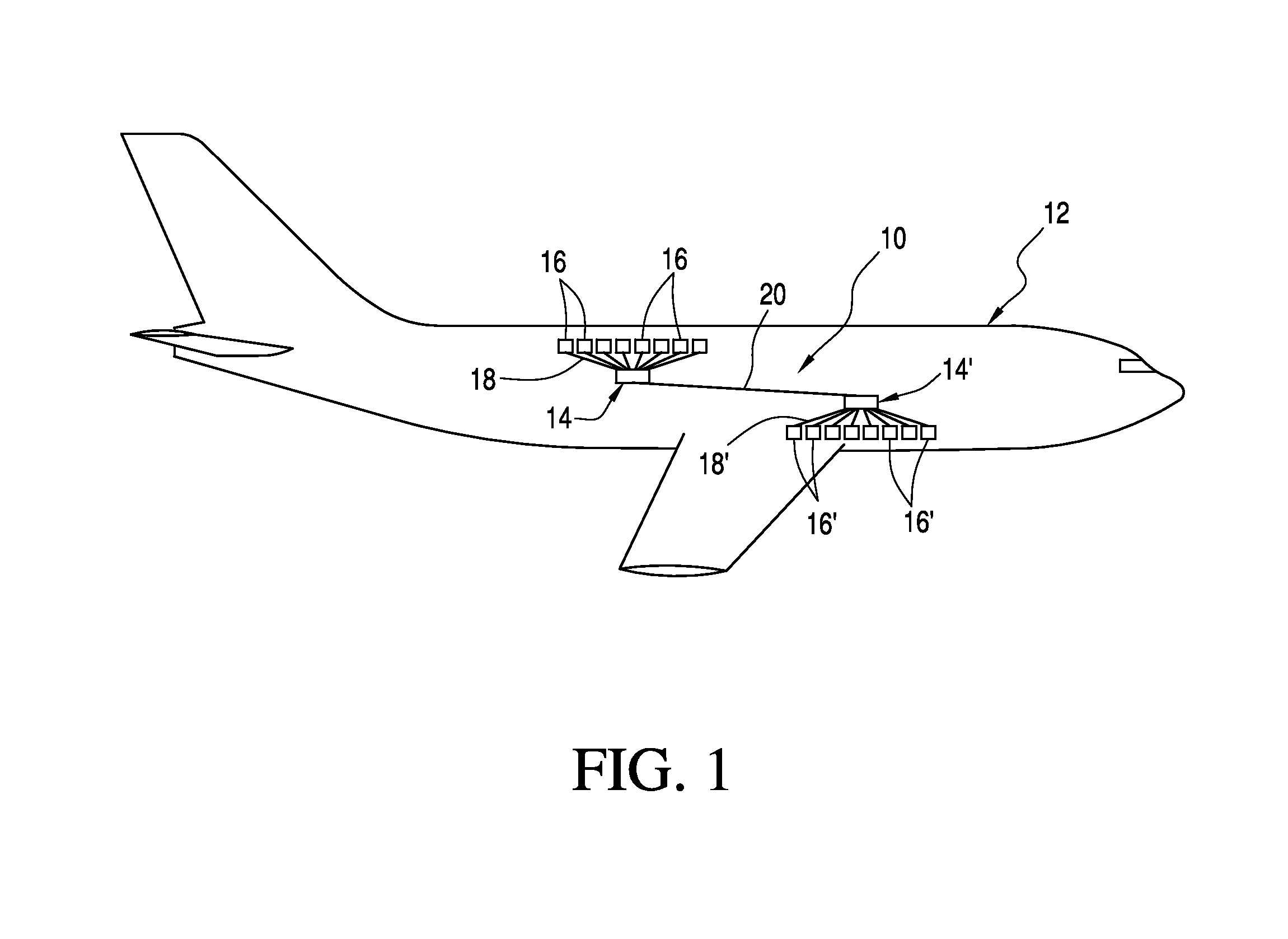
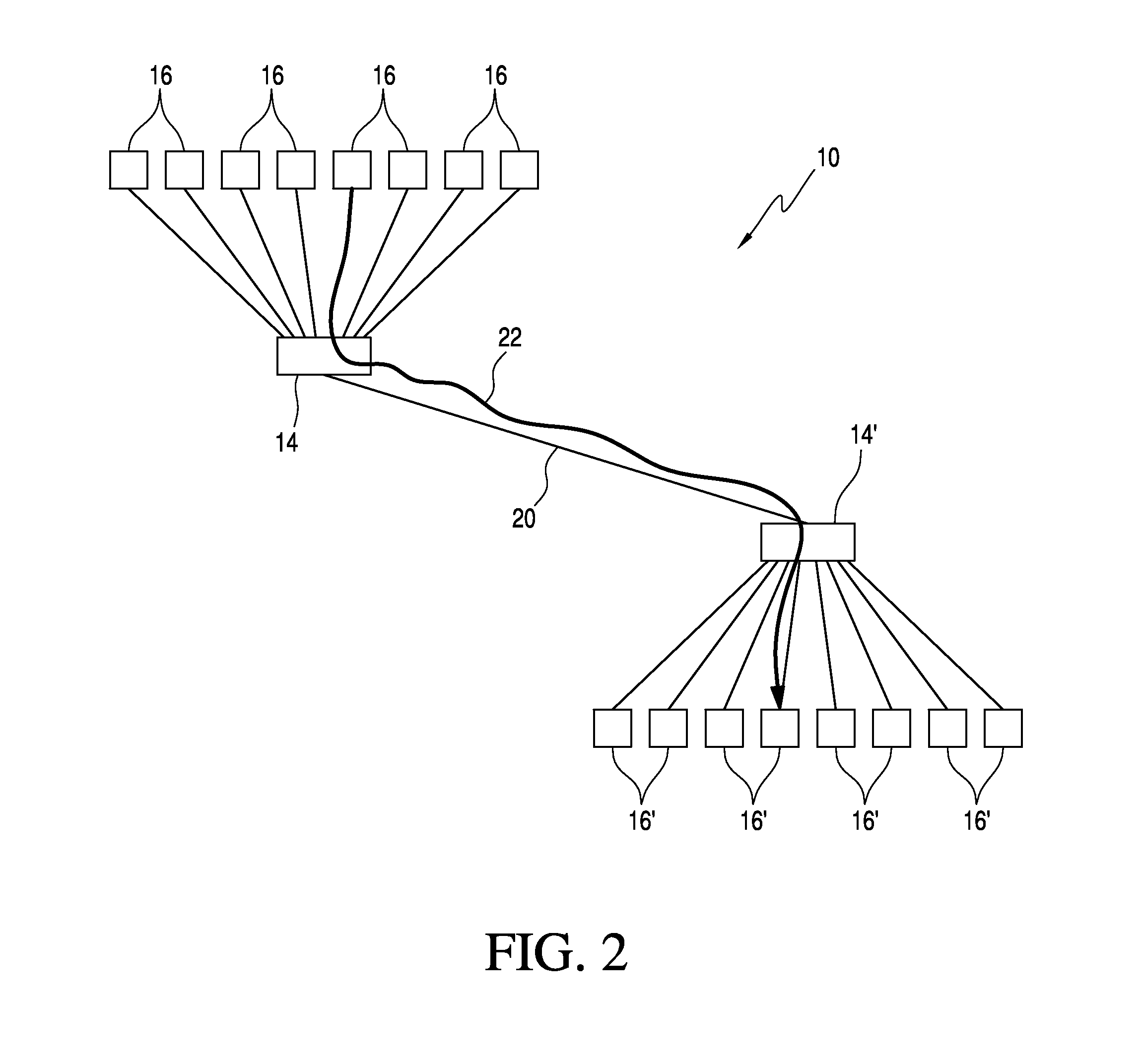
[0029]Referring now to the drawings and the characters of reference marked thereon, FIG. 1 illustrates the data network of the present invention, designated generally as 10, implemented as an avionics data network, more specifically as an AFDX Ethernet network in an aircraft 12. This illustration is greatly simplified and shows only two switches 14, 14′ and eight avionics end systems 16, 16′ connected to each switch 14, 14′. Actual data networks 10 in an aircraft may support tens and even hundreds of switches 14, 14′ and hundreds of end systems 16, 16′. This star topology minimizes wire weight as each end system 16, 16′ is connected to a nearby switch 14. Line data buses 18, 18′ connect the end systems 16, 16′ to the switches 14, 14′. Switches 14, 14′ are linked by other switches via trunk data buses 20. As used herein the term “star topology” is defined broadly to refer to a data network in which for at least one switch some portion of data received to multiple ingress ports are tr...


PUM


Abstract

A ‘per flow’ flow monitor is operatively associated with each ingress port of the switch of the data network, for monitoring the arrival data flow on each flow in defined traffic constraint envelopes containing frames. An eligibility time computation mechanism computes an eligibility time at which arriving frames on each flow will be conformant to the defined traffic envelope to the ingress port given past frame arrivals on that same flow. A holding mechanism holds the arriving frames on each flow until the eligibility time is reached. A release mechanism releases the arriving frames on a flow at the eligibility time. The flow monitor, computation mechanism, holding mechanism, and release mechanism cooperate to provide an ‘per flow’ traffic shaping function in conformance with delay and delay-jitter bound, frame loss probability, and bandwidth provisioning requirements, thus allowing the switch to enforce the traffic constraint envelope for each flow.

Description

BACKGROUND OF THE INVENTION[0001]1. Field of the Invention[0002]The present invention relates generally to avionics systems and more particularly to improved switching systems for Avionics Full-Duplex Switched Ethernet (AFDX) systems.[0003]2. Description of the Related Art[0004]Modern onboard avionics networks serve to provide data transfer between various components of an aircraft. Avionics systems typically have a variety of systems that provide data to processing components of the aircraft or exchange data among one or more components of the aircraft. For example, a variety of avionics modules may gather avionics data (e.g., sensors detecting speed, direction, external temperature, control surface positions, and the like) that is routed by the avionics system via an avionics network to one or more aircraft components such as displays, monitoring circuits, processors, and the like.[0005]In some aircraft systems, the avionics network may be constructed with an Aeronautical Radio In...

Claims


Application Information

Patent Timeline
Patent Type & Authority Patents(United States)
IPC IPC(8): H04L12/815H04L47/22
CPCH04L47/22H04L47/215H04L47/564H04L49/3018
Inventor MILLER, DAVID A.MAZUK, DANIEL E.
Owner ROCKWELL COLLINS INC
Why Eureka
Try Eureka