Anterior atlantoaxial stabilization by lateral mass screw fixation

a technology of lateral mass screw and anterior atlanto, which is applied in the field of medical devices and medical procedures, can solve the problems of high risk of infection, complex instrumentation required for such anterior approaches, and not always availabl

Inactive Publication Date: 2015-02-24
VANNEMREDDY PRASAD
View PDF15 Cites 3 Cited by
  • Summary
  • Abstract
  • Description
  • Claims
  • Application Information

AI Technical Summary

Problems solved by technology

Heretofore, anterior access has been available using transoral or transpalatal routes, which pose a high risk of infection.
Furthermore, the instrumentation required for such anterior approaches is complex and not always available.
Nevertheless, stabilization of this region using previously available anterior methods requires a second stage operation, or a second operation, since there are no effective methods currently available for anterior fixation.
This approach is not a preferred surgical procedure and is seldom used today.

Method used


Image

  • Anterior atlantoaxial stabilization by lateral mass screw fixation
  • Anterior atlantoaxial stabilization by lateral mass screw fixation
  • Anterior atlantoaxial stabilization by lateral mass screw fixation

Examples


first embodiment

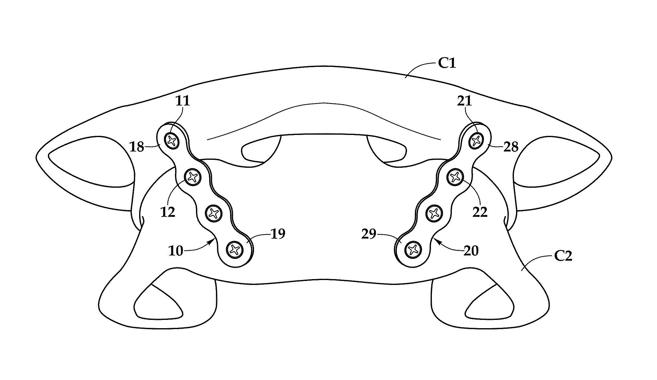
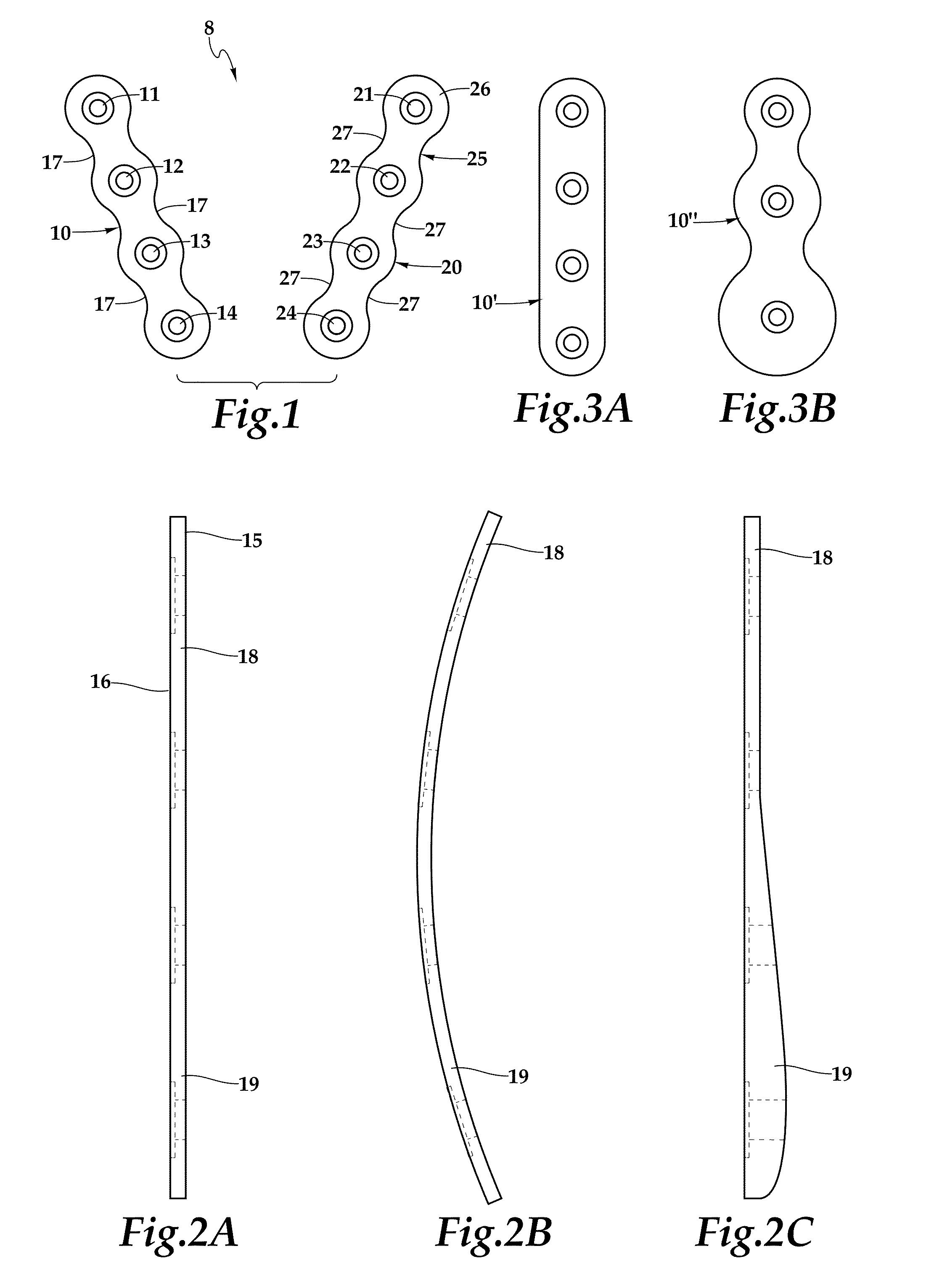
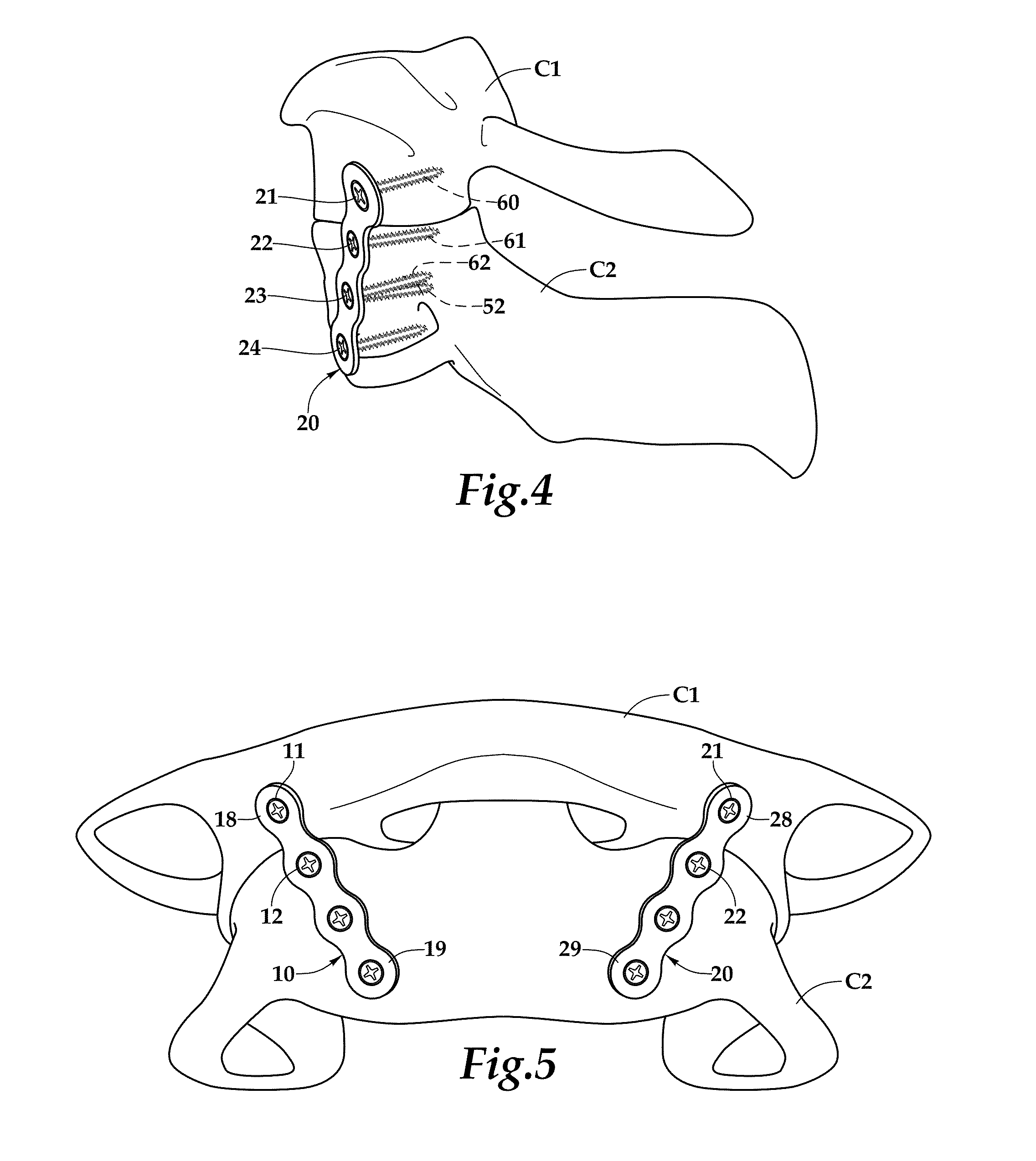
[0065]Turning to FIG. 11, another embodiment of device 308 is shown. Like numerals as compared to the first embodiment described herein, but with a 300s prefix, refer to similar elements in this embodiment. In this embodiment, device 308 may include a first plate 310, a second plate 320, and at least a third plate 330. First plate 310 may include openings 311-314 configured to receive screws to affix plate 310 to a C1 articular facet, a C2 articular facet, and the body of the C2 vertebra. Similarly, second plate 320 may include openings 321-324 configured to receive screws to affix plate 320 to the other C1 articular facet, the other C2 articular facet, and the body of the C2 vertebra.

[0066]Third plate 330 may include a plurality of openings, including at least openings 331, 332. Openings 331, 332 may be spaced such that, in use, they overlay a complementary pair of openings on plates 310 and 320, e.g., openings 313 and 323. Additionally or alternatively, third plate may include add...

second embodiment

[0072]Turning to FIG. 12, plate 330′ is shown. Plate 330′ may include openings 331′ and 334′ but not additional openings. Instead, plate 330′ may include a crossbar member 328′ between openings 331′ and 334′. Member 328′ may have a generally constant width along its length. That width preferably is less than a width of the rest of plate 330′ and may be between the plate width and the diameter of openings 331′, 334′. Like plate 330, plate 330′ may be between about 3 cm and about 4 cm long.

[0073]In one embodiment, plate 330 may be a separate, distinct member from one or both of plates 310, 320. In another embodiment, plate 330 may be joined to one or both of plates 310, 320 prior to insertion of any fasteners. For example, FIG. 13 shows an embodiment in which plate 330 includes a tab or other protrusion 335 extending downward around a perimeter of opening 324. Protrusion 335 may be configured to fit within opening 324 to prevent relative translation of plates 320, 330 when a screw is ...


PUM


Abstract

A device and method for anterior atlantoaxial stabilization may include one or more plates having a plurality of openings for receiving screws configured to screw into one or more C1 articular pillars, one or more C2 articular pillars, and the C2 body. A third cross-linking member may couple to first and second plates to provide additional rigidity and / or resistance to rotational forces. The cross-link member may be separate from one or both of the other plates. Alternatively, the cross-link member may be coupled, releasably or otherwise, to one or more of the other plates. Still further, one or more plates may be joined, e.g., via a single screw passing through openings in both plates or by making the device a unitary structure with a single, shared hole for the plates. One or more plates also may deviate from a substantially planar structure to better operatively engage the spinal features.

Description

[0001]This application claims the benefit of priority from U.S. Provisional Application 61 / 628,173, filed Oct. 26, 2011.BACKGROUND OF THE INVENTION[0002]1. Field of the Invention[0003]The present invention pertains to a medical device and a medical procedure that will improve the safety, post-operative recovery, and ease of surgery to repair upper cervical spine (vertebral column, bones) damage.[0004]2. Description of the Related Art[0005]Traditionally, atlantoaxial region fixation has been performed from a posterior approach. Heretofore, anterior access has been available using transoral or transpalatal routes, which pose a high risk of infection. Furthermore, the instrumentation required for such anterior approaches is complex and not always available.[0006]Anterior or high cervical approaches make it possible to expose the C1-C2 region, and such approaches have been used to perform excision of the odontoid process or tumors of the C2 or odontoid region. Nevertheless, stabilizatio...

Claims


Application Information

Patent Timeline
Patent Type & Authority Patents(United States)
IPC IPC(8): A61B17/70
CPCA61B17/7059
Inventor VANNEMREDDY, PRASAD
Owner VANNEMREDDY PRASAD
Why Eureka
Try Eureka