Controlled fracture connections for stents

a technology of stents and connections, applied in the field of intraluminal stent design, can solve the problems of significant stress on the stent by loading conditions, and achieve the effects of improving flexibility, maintaining or improving the patency of the stent, and improving the resistance to fractur

Inactive Publication Date: 2015-02-24
COVIDIEN LP
View PDF79 Cites 31 Cited by
  • Summary
  • Abstract
  • Description
  • Claims
  • Application Information

AI Technical Summary

Benefits of technology

[0007]In certain embodiments the invention provides a stent which may be implanted in the vessel lumen of a subject in order to maintain or improve the patency of the vessel. Some embodiments of the invention provide a stent with improved resistance to fracture in certain implantation sites, as well as improved flexibility suitable for traversing through and deployment in tortuous vasculature. For example, certain stents of the invention may be used in the superficial femoral or iliac arteries. The stent may be expandable and thus have a first (smaller) and second (larger) diameter. The first diameter may be suitable for delivery of the stent to its implant site, while the second diameter, i.e., the deployed expanded diameter, is approximately the diameter of the vessel lumen at the implant site and is thus suitable for maintaining the vessel patency. According to a first aspect of the invention, a stent for implantation into a vessel comprising a plurality of annular segments collectively forming tubular shape, characterized by at least first and second adjacent annular segments each defined by a plurality of struts; and at least one joint interconnecting respective struts of the first and second segments on a non-permanent basis. In one embodiment, the interconnecting joint comprises a first male interlocking structure and a second female interlocking structure. In another embodiment, the respective struts of the first and second segments each comprise a hole and the interconnecting joint projects through the hole in the respective struts of the first and second segments. In still other embodiment, the interconnecting joint has a first end and a second end, and the first and second ends are each thicker than the diameter of one of the holes in the respective struts of the first and second segments. In other embodiments the interconnecting joint separates after the stent is deployed or at least a portion of the stent may comprise shape memory material such as nitinol or a shape memory polymer.

Problems solved by technology

Loading conditions generate significant amounts of stress on the stent involving torsion, extension, compression and flexion.

Method used


Image

  • Controlled fracture connections for stents
  • Controlled fracture connections for stents
  • Controlled fracture connections for stents

Examples


Embodiment Construction

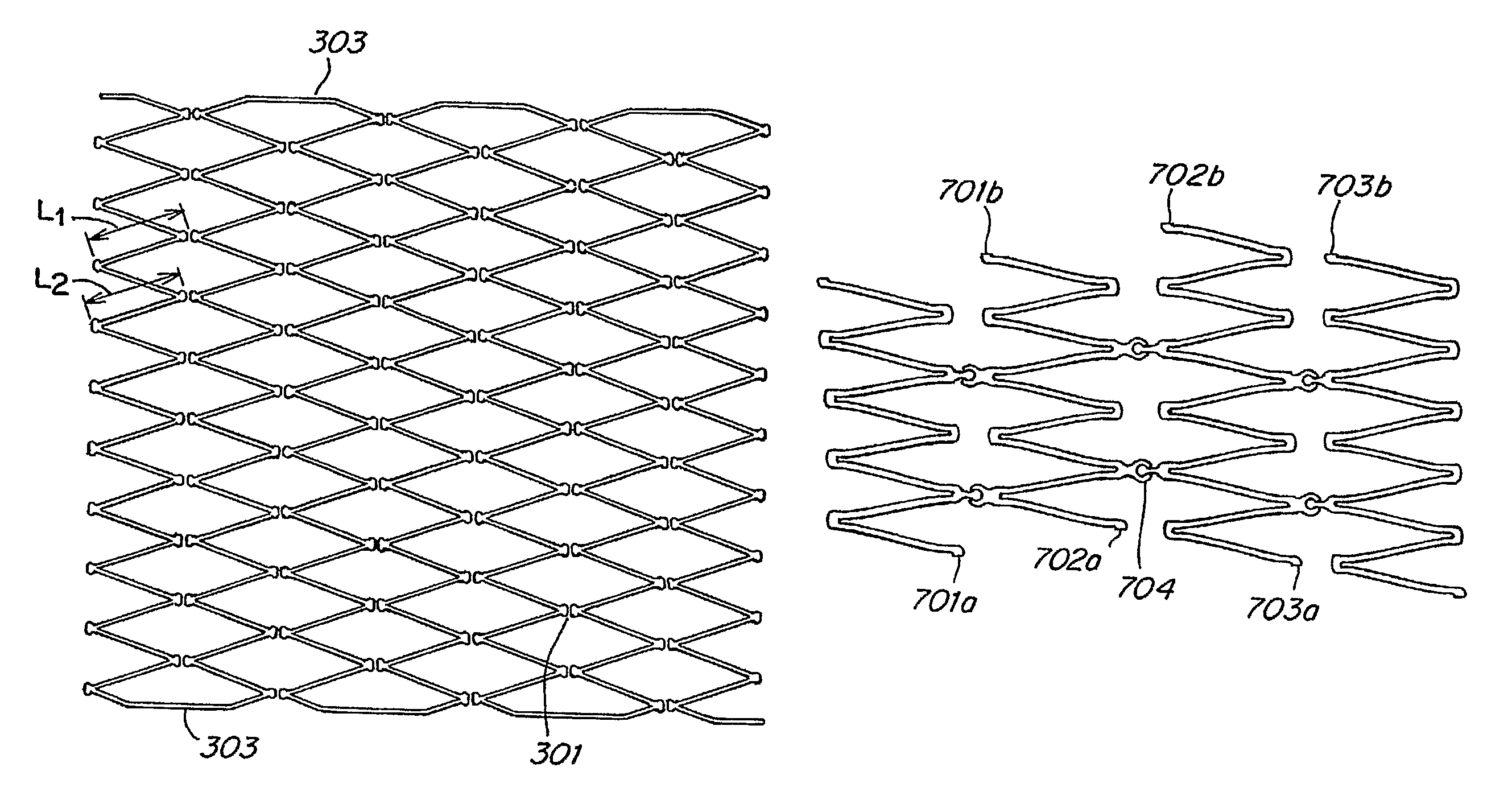
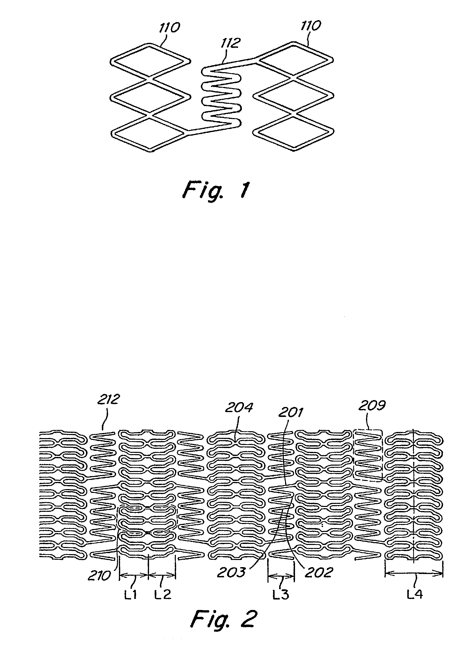
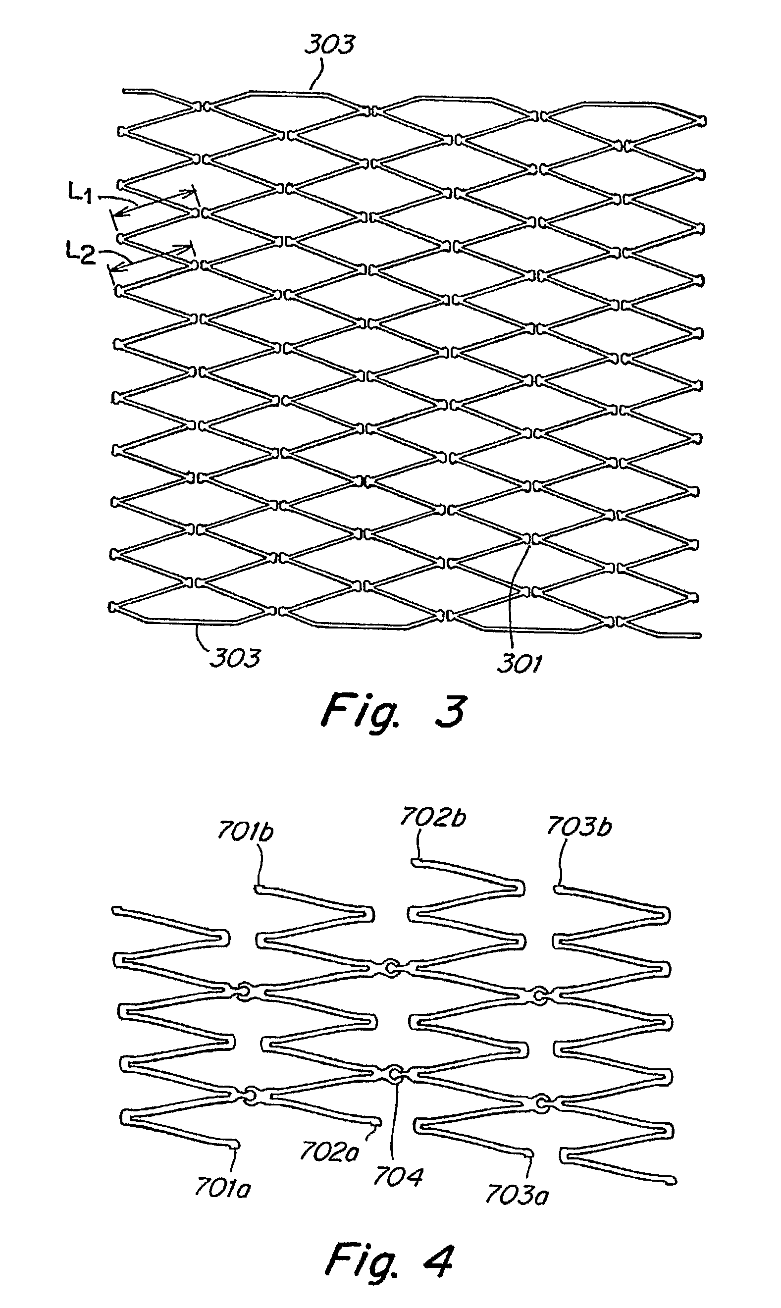
[0016]The stents of the invention are designed comprising at least one controlled fracture location and, in certain embodiments, controlled timing of the fracture. As such, the connection design and materials are suitable to provide the stent with improved resistance to fatigue fractures at uncontrollable locations which can happen with stents presently in use. Fatigue fracture is a particular problem with stents deployed in tortuous vessels which stents are constantly subjected to torsion, twisting, bending and compression. Over time, the forces cause the stent to fatigue and break, sometime allowing jagged struts and end to pierce the adjacent vessel or hang into the lumen attracting thrombi. Such breakage can also compromise the support provided by the stent. Thus, the stents of the invention are designed to separate in such a manner so that when separation occurs the separation does not expose fragmented or jagged material and, importantly, the circumferential support provided b...


PUM

PropertyMeasurementUnit
thicknessaaaaaaaaaa
widthaaaaaaaaaa
circumferenceaaaaaaaaaa

Abstract

The invention provides for intra-luminal stents, especially stent having controlled fracture connection, as well as, methods of making and using the same. In one embodiment, a stent for implantation into a vessel has a plurality of annular segments collectively forming tubular shape, characterized by at least first and second adjacent annular segments each defined by a plurality of struts and at least one joint interconnecting respective struts of the first and second segments on a non-permanent basis.

Description

RELATED APPLICATIONS[0001]This application claims the benefit of PCT Application Serial No. PCT / US2006 / 015596, filed Apr. 25, 2006; which claims priority of U.S. Provisional Application Ser. No. 60 / 674,859, filed Apr. 25, 2005, the disclosures of all of which are incorporated herein by reference in their entirety as if fully set forth herein.FIELD OF THE INVENTION[0002]The invention relates generally to the field of prosthetic medical devices, and, more particularly to designs for intra-luminal stents.BACKGROUND OF THE INVENTION[0003]Stents are prosthetic devices implanted within a subject's vessel lumen to maintain the patency of the vessel. Typically stents are comprised of cylindrical members, which are capable of expanding from a smaller diameter to a larger diameter. The stent is typically implanted within a patient's vasculature by a minimally invasive procedure using a catheter and guide wire. The catheter serves as a delivery device to transport the stent to its implantation...

Claims


Application Information

Patent Timeline
Patent Type & Authority Patents(United States)
IPC IPC(8): A61F2/06A61F2/91A61F2/915
CPCA61F2/915A61F2/91A61F2002/91525A61F2002/91533A61F2002/91558A61F2002/91591A61F2210/0004A61F2250/0071A61F2/89A61F2002/9155
Inventor MA, JIANLUKHOUENGBOUA, OTTGRAFOV, ALEX
Owner COVIDIEN LP
Why Eureka
Try Eureka