Network system, station-side apparatus, and method of controlling communications

a network system and station-side technology, applied in the field of station-side devices, can solve the problems that the bandwidth of communication to actually send and receive data will become unfair among a plurality of wavelengths used in the pon system, and achieve the effect of high transmission efficiency

Active Publication Date: 2015-02-24
HITACHI LTD
View PDF7 Cites 2 Cited by
  • Summary
  • Abstract
  • Description
  • Claims
  • Application Information

AI Technical Summary

Benefits of technology

[0016]This invention has been made in view of this problem and a primary object of this invention is to achieve wavelength assignment to ONUs that can reduce the unfairness in the communication bandwidth among the wavelengths in a WDM / TDM-PON system.
[0018]According to an embodiment of this invention, the unfairness in communication bandwidth among wavelengths can be reduced even if the network system includes ONUs communicating at different effective transmission rates in transmission and receiving.

Problems solved by technology

However, if a WDM (Wavelength-Division Multiplexing) PON system employing selectable FEC code rate for each ONU simply assigns wavelengths based on the number of registered ONUs, communication bandwidths (transmission rates) to actually send and receive data will become unfair among a plurality of wavelengths used in the PON system.

Method used


Image

  • Network system, station-side apparatus, and method of controlling communications
  • Network system, station-side apparatus, and method of controlling communications
  • Network system, station-side apparatus, and method of controlling communications

Examples


embodiment 1

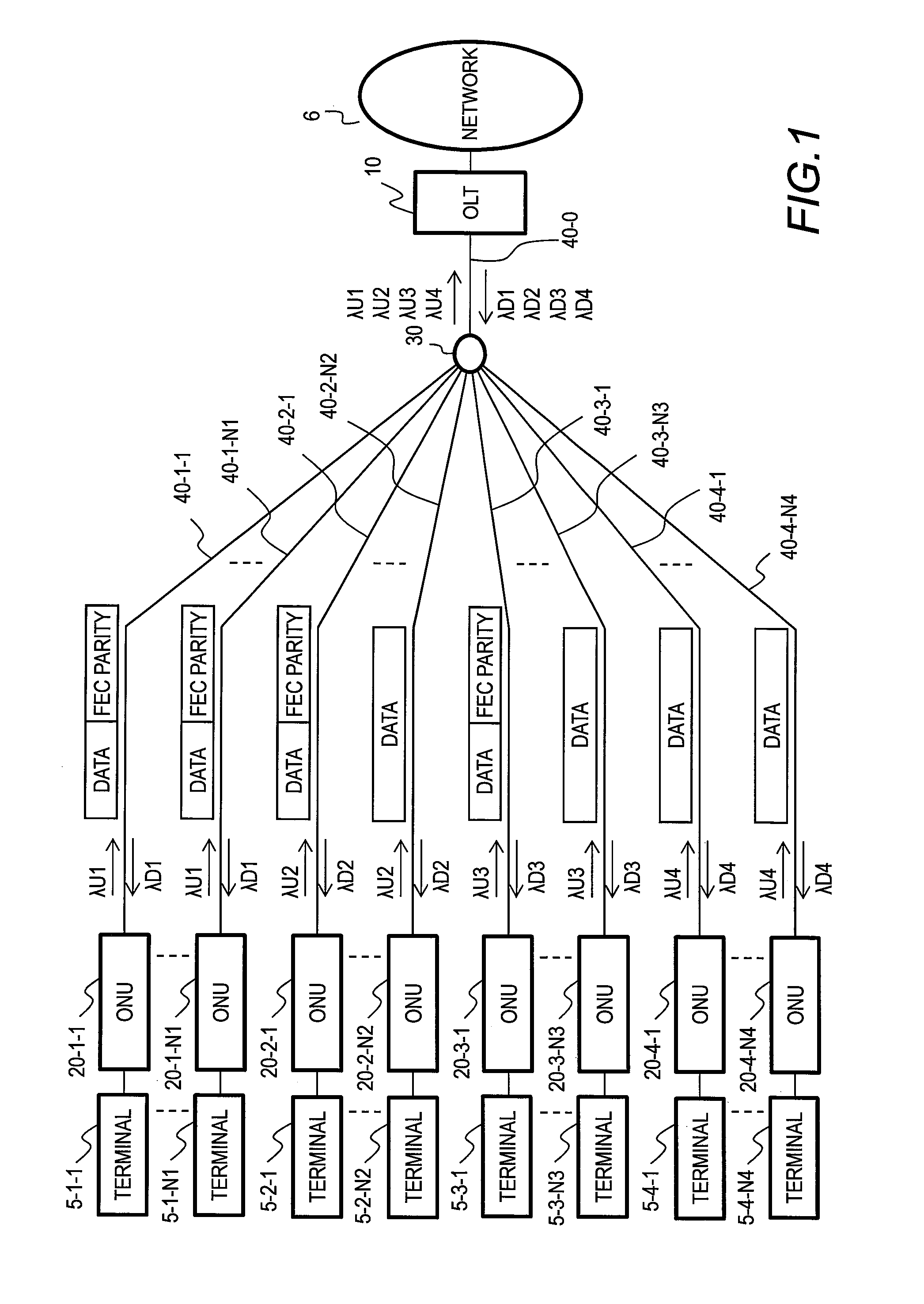
[0033]FIG. 1 is a block diagram illustrating an optical access network employing the WDM / TDM-PON in Embodiment 1.

[0034]The optical access network in Embodiment 1 includes an OLT 10, an optical splitter 30, a plurality of ONUs 20 (20-1-1 to 20-4-N4), and a plurality of terminals 5 (5-1-1 to 5-4-N4). The OLT 10 is an optical line terminal and the ONU 20 is an optical network unit.

[0035]The OLT 10 is connected to the optical splitter 30 via a trunk line optical fiber 40-0. The optical splitter 30 is connected to the ONUs 20-1-1 to 20-4-N4 via branch line optical fibers 40-1-1 to 40-4-N4. The terminals 5-1-1 to 5-4-N4 are connected to their respective ONUs 20-1-1 to 20-4-N4.

[0036]Next, methods of downstream transmission and upstream transmission are described. The ONUs 20-1-1 to 20-1-N1 communicate with the OLT 10 using a downstream wavelength λD1 and an upstream wavelength λU1. The ONUs 20-2-1 to 20-2-N2 communicate with the OLT 10 using a downstream wavelength λD2 and an upstream wave...

embodiment 2

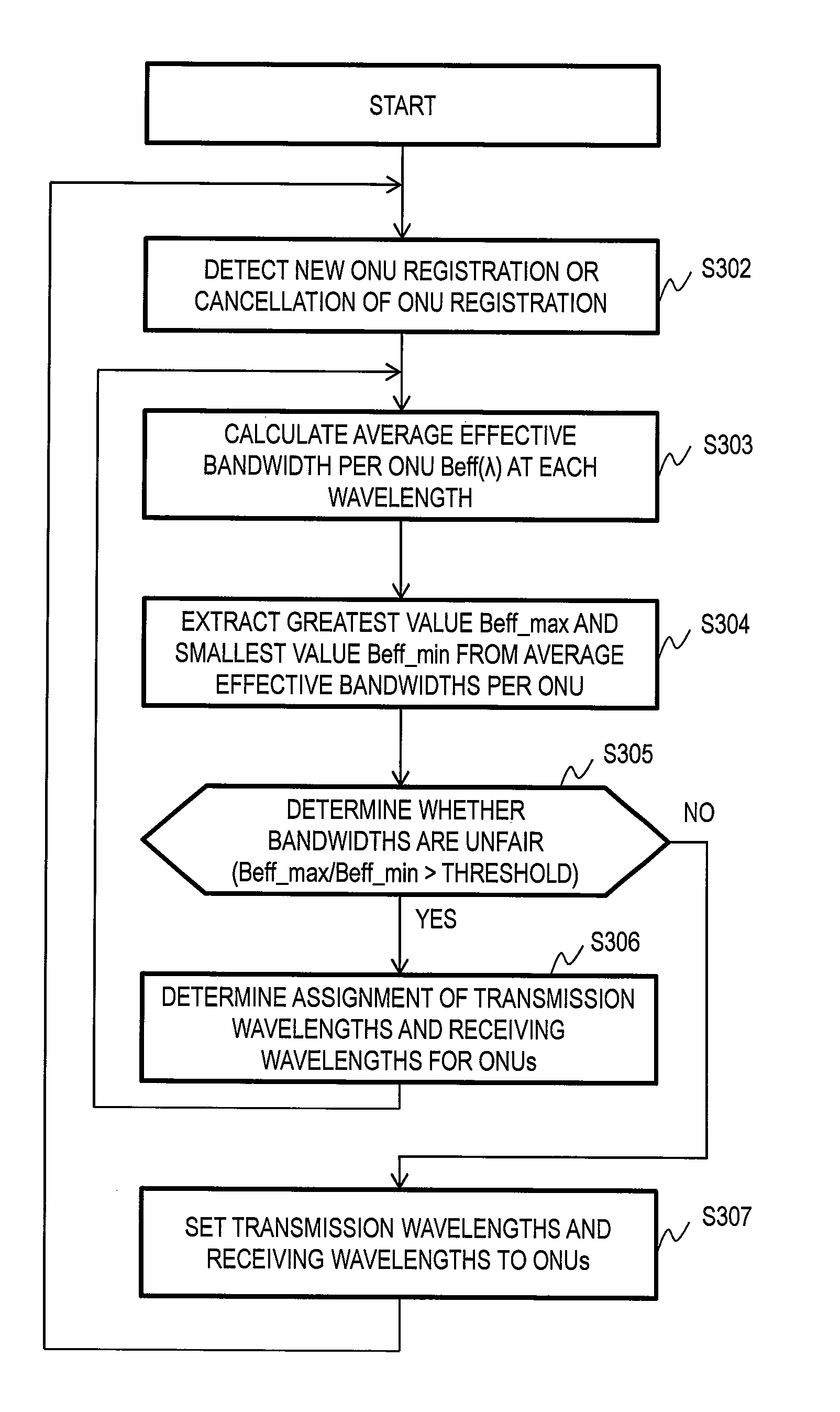
[0165]The foregoing Embodiment 1 is an embodiment to achieve wavelength assignment so that the average effective bandwidth per ONU 20 will be fair among the wavelengths in a WDM / TDM-PON system including ONUs 20 having different FEC code rates 1712.

[0166]Embodiment 2 is an embodiment to achieve wavelength assignment so that the average effective bandwidth per ONU 20 will be fair among the wavelengths in a WDM / TDM-PON system including ONUs 20 having different transmission rates.

[0167]A PON system supporting a plurality of transmission rates is defined by existing standards; for example, the 10G-EPON and the 1G-EPON may be implemented in the same optical network. Such an optical network includes ONUs 20 having a transmission rate of 10 Gbps and ONUs 20 having a transmission rate of 1 Gbps together. Hereinafter, differences from Embodiment 1 are mainly described.

[0168]FIG. 9 is a block diagram illustrating an optical access network employing the WDM / TDM-PON in Embodiment 2.

[0169]Before ...


PUM


Abstract

An aspect of this invention is a network system including subscriber apparatuses and a station-side apparatus for communicating with the subscriber apparatuses. The station-side apparatus communicates with the subscriber apparatuses using wavelengths. The station-side apparatus determines a wavelength to be used by each of at least one subscriber apparatus of the subscriber apparatuses based on effective transmission rates used by the subscriber apparatuses in communications with the station-side apparatus.

Description

CLAIM OF PRIORITY[0001]The present application claims priority from Japanese patent application JP2012-269224 filed on Dec. 10, 2012, the content of which is hereby incorporated by reference into this application.BACKGROUND OF THE INVENTION[0002]This invention relates to a station-side apparatus.[0003]The recent prevalence of the Internet is enhancing the demand for higher-speed network communications. To meet this demand for higher-speed communications, ADSL (Asymmetric Digital Subscriber Line) or PON (Passive Optical Network) is growing. The PON includes B-PON (Broadband PON), E-PON (Ethernet PON), and G-PON (Gigabit-capable PON).[0004]The PON is a network system which connects an accommodation station (OLT: Optical Line Terminal) installed in a vendor's station and network units (ONUs: Optical Network Units) installed in user premises; in the PON, the signal in an optical fiber connected to the OLT is split into a plurality of fibers with an optical splitter; the plurality of fib...

Claims


Application Information

Patent Timeline
Patent Type & Authority Patents(United States)
IPC IPC(8): H04J14/00H04J14/02
CPCH04J14/0227H04J14/0246H04J14/0247H04J14/025H04J14/0252H04J14/026H04J14/0282H04J14/0254H04J14/0257H04J14/0267
Inventor SUGAWA, JUNODAKA, TOSHIYUKITOYODA, HIDEHIRO
Owner HITACHI LTD
Why Eureka
Try Eureka