Component catch for crash robustness

a technology of component catch and robustness, which is applied in the direction of combustion air/fuel air treatment, fuel injection apparatus, charge feed system, etc., can solve the problems of increasing production costs and/or overall weight of the engine, shearing of the joint with the lower intake manifold, etc., to reduce the load transfer and impact with surrounding components, reduce shear force propagation, and reduce the effect of overall weigh

Active Publication Date: 2015-03-03
FORD GLOBAL TECH LLC
View PDF15 Cites 2 Cited by
  • Summary
  • Abstract
  • Description
  • Claims
  • Application Information

AI Technical Summary

Benefits of technology

[0003]Modifications to an intake manifold have been made to mitigate motion of the intake manifold during collisions. Previous approaches employ the addition of components to the top of the intake manifold to either increase structural rigidity, or to guide collision forces away from surrounding components. Other prior approaches employ added mounting hardware to strengthen the joint between the upper intake manifold and the lower intake manifold. These additional components or modifications to the manufacture of the intake manifold may increase production costs and / or overall weight of the engine.
[0005]The inventors have recognized the above described issues and herein describe a potential solution. A shear catch is disclosed that employs components fitted underneath the intake manifold between the manifold and the cam cover. The shear catch comprises components that may reduce shear forces propagated along the length of the intake manifold that may potentially result in disengagement of the upper intake manifold from the lower intake manifold. In some embodiments, the shear catch comprises an upper component mounted to the underside of the upper intake manifold and a lower component mounted to the top side of the cam cover. The upper and lower components may engage in various ways, such as by snagging, hooking, interlocking, catching, deforming one another, among others. In this way, the technical effect of transferring load to intermediate components may be achieved.
[0006]In an embodiment, the shear catch may manage the deformation of intermediate parts to reduce impact and load transfer into components proximate to the manifold during impact events. In one example, this may be accomplished by adding structural features to the intermediate parts and a surrounding part (e.g. cam covers, lower intake manifold, cylinder head), that engage during the impact. These features cause deformation of the intermediate part, reducing load transfer and impact with surrounding components. In arranging the upper and lower components between the intake manifold and the cam cover there is clearance between the upper and lower components. This clearance may allow for ease of assembly, service, and for a decrease in noise, vibration, and harshness (NVH) characteristics. The location of a shear catch may also reduce the need for an additional crash bracket(s) or additional fastening location(s), thus reducing cost and weight. However, in other examples, additional structural features and components may be added to the intake manifold and / or cam cover in addition to a shear catch.

Problems solved by technology

In the event of a collision, the upper intake manifold may be subjected to excessive shear forces, possibly resulting in shearing of the joint with the lower intake manifold.
These additional components or modifications to the manufacture of the intake manifold may increase production costs and / or overall weight of the engine.

Method used


Image

  • Component catch for crash robustness
  • Component catch for crash robustness
  • Component catch for crash robustness

Examples


first embodiment

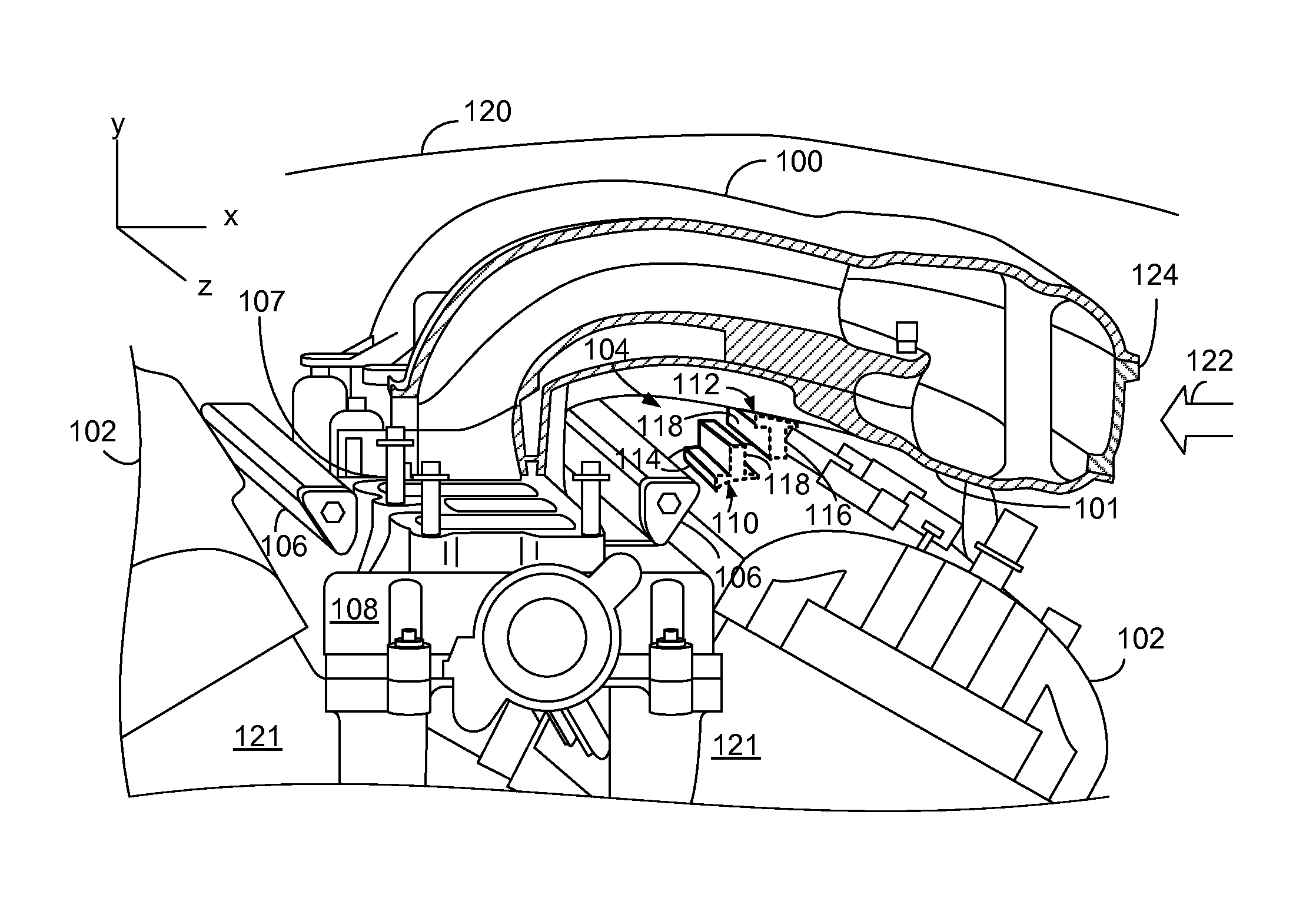
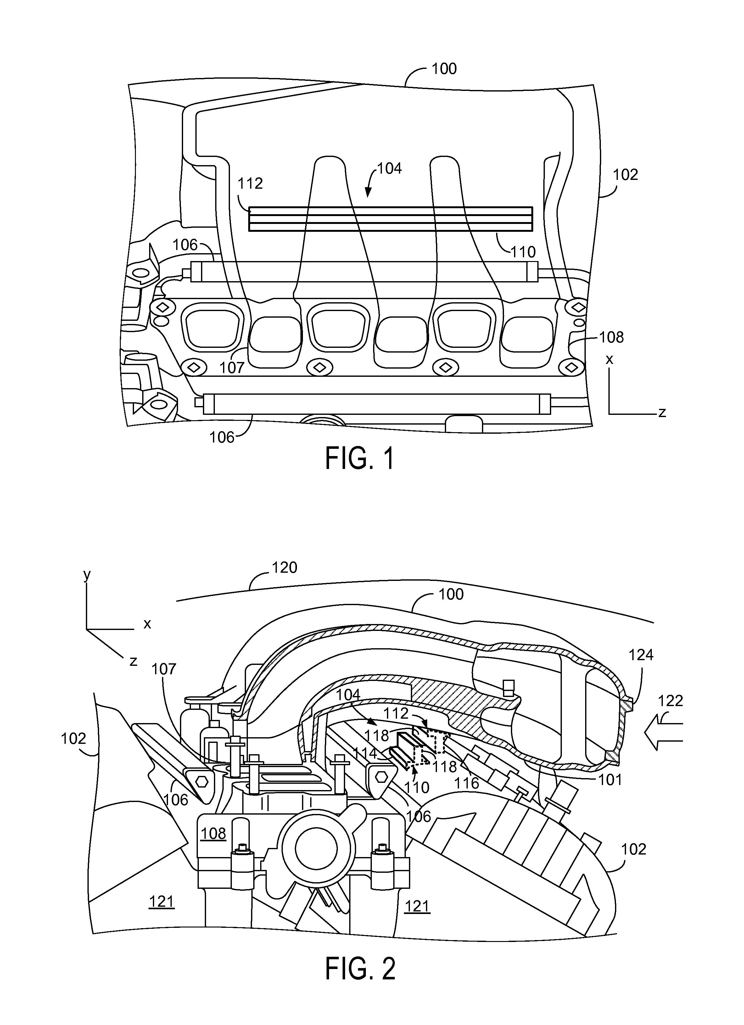
[0027]FIG. 2 shows a second view of the shear catch 104. The shear catch comprises an upper component 112, having a rib shape, which is affixed to the underside 101 of the upper intake manifold 100. The upper component 112 may be bolted or otherwise adhered to the upper intake manifold, or may be molded as a component of the upper intake manifold 100. A lower component 110, having a rib shape, is attached to the cam cover 102. The rib shape comprises a substantially linear upright lip 116, formed on a base structure 114 that may serve as a supportive flange capable of further dispersing shear forces, or may provide a surface with which to bolt or mold the upper and lower components to the upper intake manifold or cam cover respectively. The base structure may extend in the x-direction on either side of the upright portion of the rail shape. The base may also be molded or shaped such that it rests evenly on the cam cover or upper intake manifold by matching the intrinsic curvature or...

second embodiment

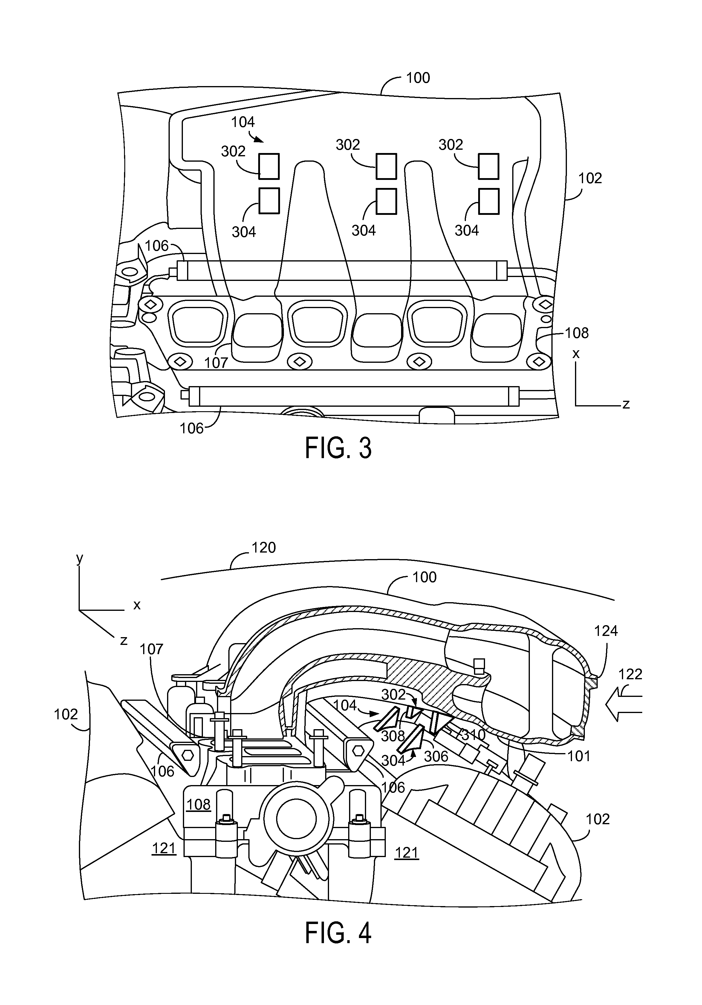
[0043]In FIG. 4, two matched pairs of upper component 302 and lower component 304 are shown along the length of the engine for the sake of simplicity of the drawings. The engaging surface of the upper component 308 and the engaging surface of the lower component 306 are positioned opposite each other but do not touch under normal circumstances. Upon impact, an excessive shear force may be applied to the upper intake manifold 100 resulting in the engaging surfaces 306 and 308 contacting. The triangular shape of the shear catch of the second embodiment may function as a brace, transferring shear forces through the extending portion 310 to the cam cover or underside 101 of the upper intake manifold 100.

[0044]It should be appreciated that more matched pairs may be affixed to the cam cover and upper intake manifold. Furthermore, the size of each component of shear catch 104 may vary. Though depicted here as triangles, the upper catch and lower catch may comprise, rectangular, square, hoo...


PUM


Abstract

Systems are disclosed to restrain movement of engine components in the event of a collision. A system may comprise an upper intake manifold; a cam cover; a shear catch located between the upper intake manifold and the cam cover; an upper component of the shear catch is arranged on the upper intake manifold; a lower component of the shear catch is arranged on the cam cover; and the upper component and the lower component are arranged opposite each other such that they engage when the upper intake manifold is subjected to shear forces. Variations to the size, arrangement, and shape of a shear catch are disclosed herein.

Description

TECHNICAL FIELD[0001]The present application relates to restraint of engine component movement upon impact.BACKGROUND AND SUMMARY[0002]A vehicle intake system may comprise an upper intake manifold joined to a lower intake manifold. The upper intake manifold may be positioned over the cam cover. Fuel rails for supplying fuel to the respective cylinders may be mounted in front and in the rear of the joint between the upper intake manifold and the lower intake manifold. In the event of a collision, the upper intake manifold may be subjected to excessive shear forces, possibly resulting in shearing of the joint with the lower intake manifold.[0003]Modifications to an intake manifold have been made to mitigate motion of the intake manifold during collisions. Previous approaches employ the addition of components to the top of the intake manifold to either increase structural rigidity, or to guide collision forces away from surrounding components. Other prior approaches employ added mounti...

Claims


Application Information

Patent Timeline
Patent Type & Authority Patents(United States)
IPC IPC(8): F02M35/10
CPCF02M35/10288F02M35/161F02F7/006F02M35/10078F02M35/104F02M63/0275
Inventor KILBY, JOHN G.RENO, IV, GEORGE LOUISPETERS, EDWARD WILLIAMDESAI, NARENDRAFORBES, ROBERT J.SNOW, CHRISTOPHER TODD
Owner FORD GLOBAL TECH LLC
Why Eureka
Try Eureka