
Vehicle auxiliary lighting system

a technology for auxiliary lighting and vehicles, applied in fixed installations, lighting and heating apparatus, lighting support devices, etc., can solve the problems of one-sided danger to a person, lack of lights on the right or left sides of vehicles, and difficulty in viewing vehicles from either side, so as to increase the safety margin and the effect of safety

Active Publication Date: 2015-03-03
HANEY CURTIS J
View PDF16 Cites 8 Cited by
  • Summary
  • Abstract
  • Description
  • Claims
  • Application Information

AI Technical Summary

Benefits of technology

The patent is about a vehicle auxiliary lighting system that includes colored side lights that automatically illuminate in synchrony with a vehicle light. This system provides an increased margin of safety for both pedestrians and other motorists. The technical effect of this invention is to improve safety on the road by adding a unique and effective safety feature to vehicles.

Problems solved by technology

Typically, most vehicles are operated in close proximity to people and other vehicles which present a one-sided danger to a person in the event of an accident that involves a vehicle hitting a person.
One such deficiency is the absence of lights on the right or left sides of a vehicle.
Conventional front and rear lights provide adequate safety considerations when viewing a vehicle from the front or rear, but it is difficult to see the lights when viewing the vehicle from either side.
This is a significant problem in that vehicles and people travel in many directions simultaneously, and there is constant interaction between people approaching vehicles from the front, rear or sides.

Method used


Image

  • Vehicle auxiliary lighting system
  • Vehicle auxiliary lighting system
  • Vehicle auxiliary lighting system

Examples


Embodiment Construction

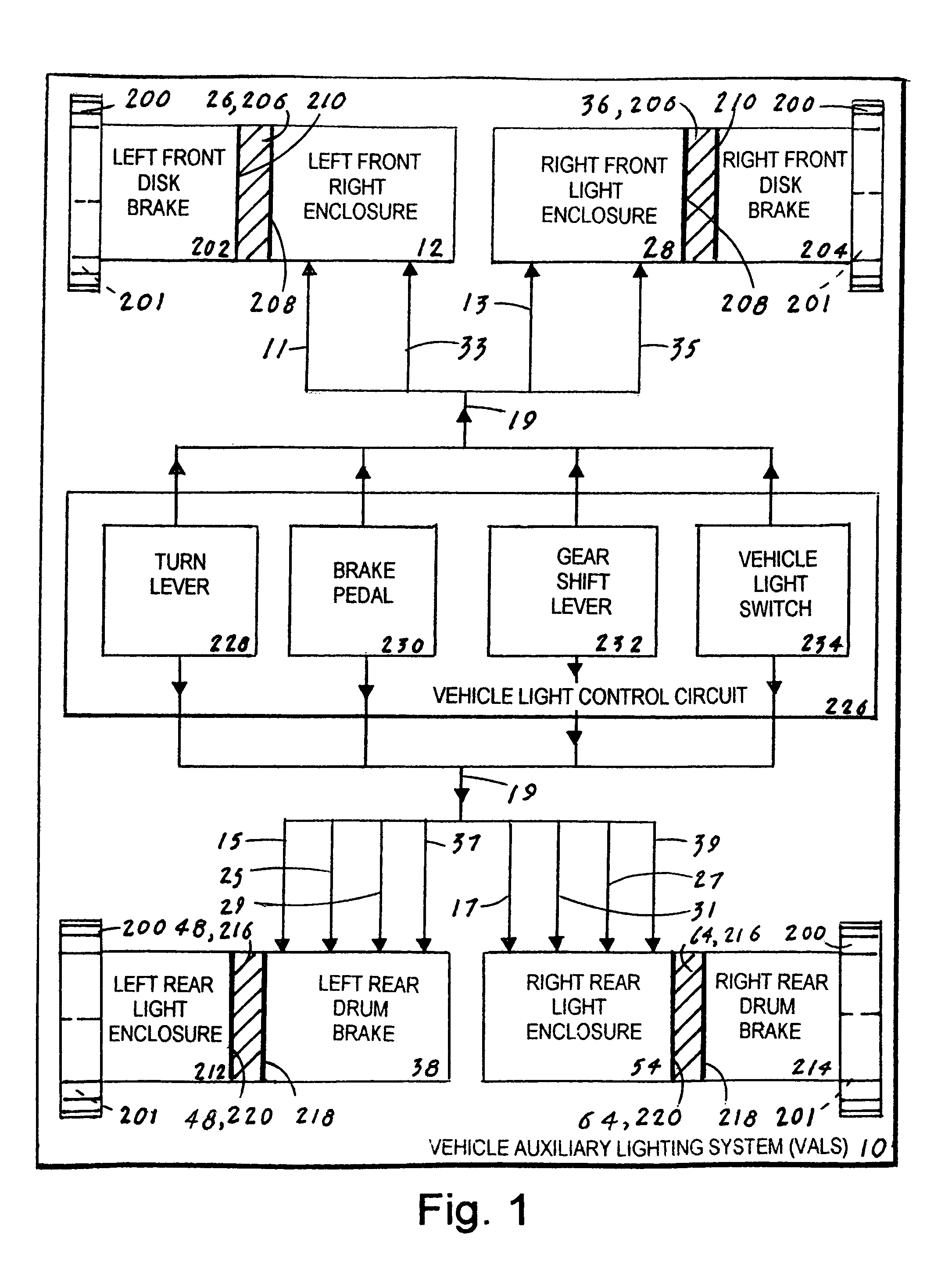
[0038]The best mode for carrying out the invention is presented in terms that disclose a preferred embodiment of a vehicle auxiliary lighting system 10 (VALS 10). The VALS 10 includes a set of left and right side lights that when illuminated provide an additional margin of safety to both pedestrians and other motorists.

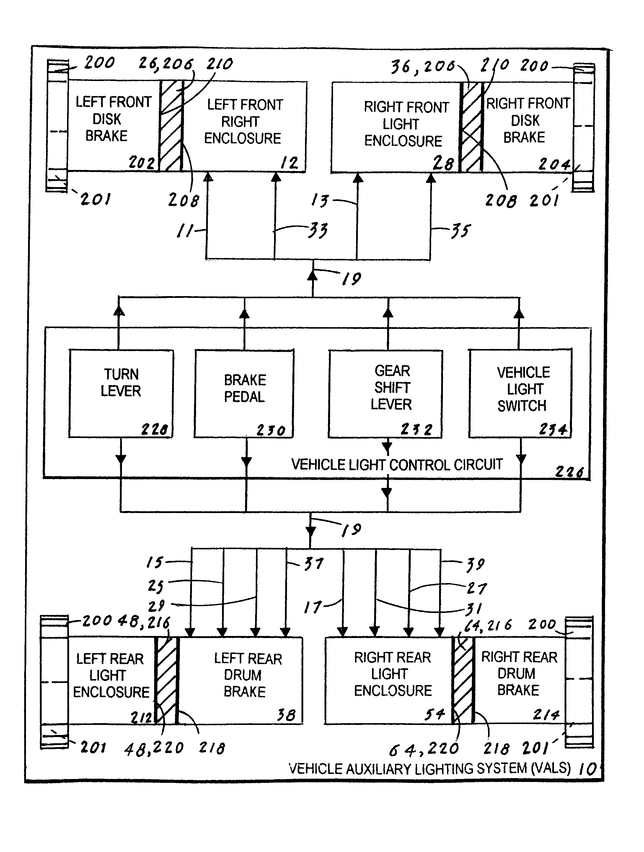
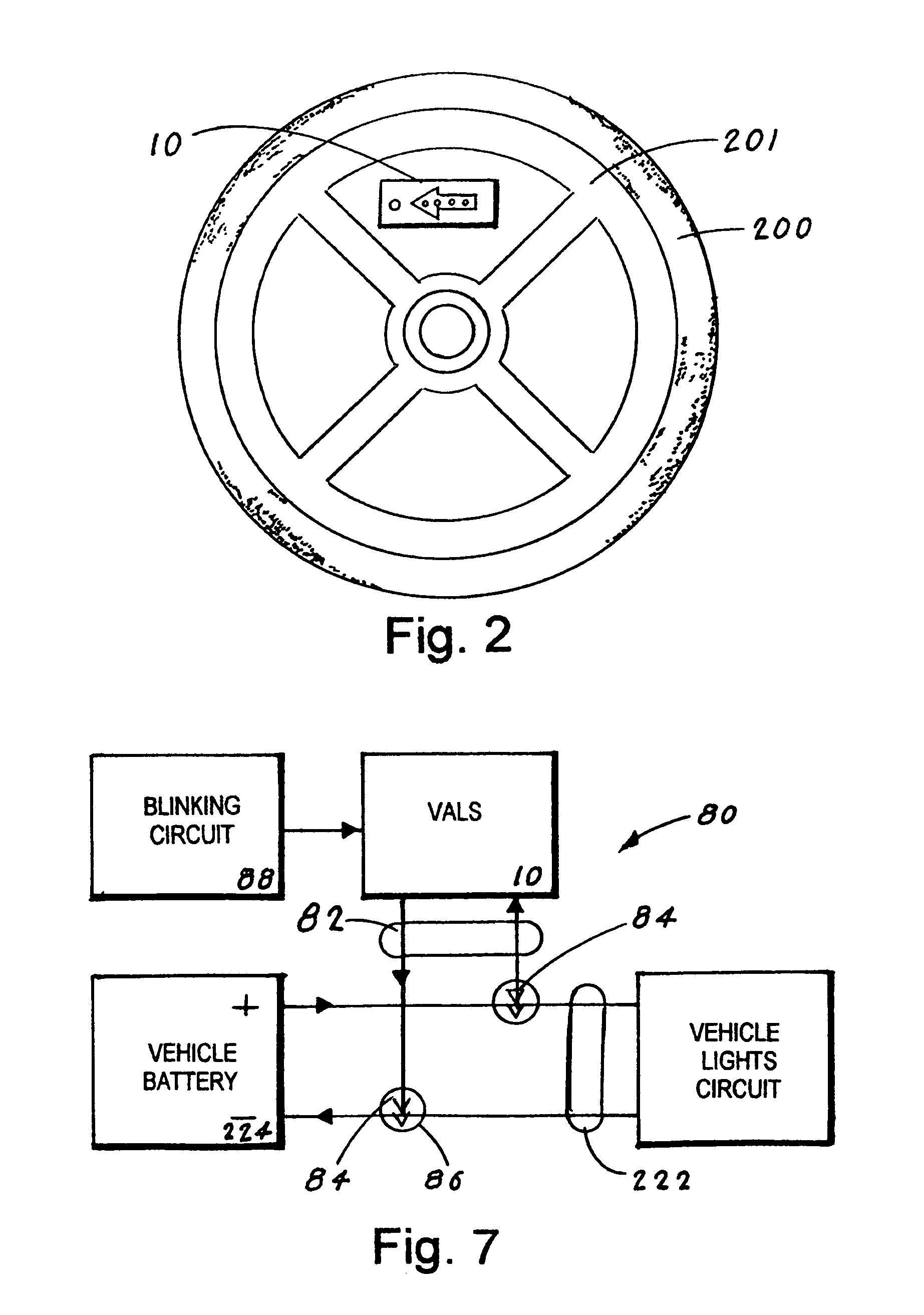
[0039]The preferred embodiment, as shown in FIGS. 1-11, is designed to operate in combination with existing vehicle elements that include for purposes of this disclosure: a tire 200 that is mounted to a vehicle wheel 201, a left front disk brake 202, a right front disk brake 204, a left rear drum brake 212, a right rear drum brake 214, a vehicle battery 224 and a vehicle light control circuit 226. The VALS 10 can be designed to function with either a pair of front disk brakes and a pair of rear disk brakes, with a pair of front disk brakes and a pair of rear drum brakes, or with a pair of front drum brakes and a pair of rear drum brakes. For purposes of brevity this i...


PUM


Abstract

A vehicle auxiliary lighting system (VALS 10) having attached to the side of a vehicle a set of side lights that automatically illuminate in synchrony with a corresponding set of vehicle lights are activated by a vehicle driver. The side lights are attached to four moisture-resistant enclosures namely: a left front light enclosure (12), a right front light enclosure (28), a left rear light enclosure (38) and a right rear light enclosure (54). The enclosures, which are attached to a structure adjacent a set of disk brakes and a set of drum brakes, are viewed through openings on a set of spoked vehicle wheels. The side lights, which correspond to the vehicle's front facing lights, produce an amber light; the side lights that correspond to the vehicle's rear facing lights produce a red light; and the side light that corresponds to a vehicle's reverse light produces a white light. By utilizing the VALS (10) the margin of safety for both pedestrians and other motorists is increased.

Description

[0001]This application claims priority of Provisional Patent Application No. 61 / 283,301 filed Dec. 2, 2009.TECHNICAL FIELD[0002]The invention generally pertains to vehicle lighting systems, and more particularly to a vehicle auxiliary lighting system (VALS) having a set of a light enclosures that are attached to a vehicle's front and rear brakes and that are visible through side openings in the vehicle's wheel.BACKGROUND ART[0003]The most widely used and popular means of transportation throughout the world is a motorized vehicle, such as a personal automobile or a public transportation vehicle. One of the most important considerations when designing and operating any motorized vehicle is safety. Typically, most vehicles are operated in close proximity to people and other vehicles which present a one-sided danger to a person in the event of an accident that involves a vehicle hitting a person.[0004]As a result, vehicle designers and manufacturers have allocated significant resources ...

Claims


Application Information

Patent Timeline
IPC IPC(8): B60Q1/12B60Q1/56
CPCB60Q1/326B60Q1/38B60Q1/44B60Q2400/30
Inventor HANEY, CURTIS J.
Owner HANEY CURTIS J
Learn More