Apparatus and method for regulating flow through a pumpbox

a pumpbox and apparatus technology, applied in the field of pumpboxes, can solve the problems of more difficult ore sizing

Inactive Publication Date: 2015-03-03
SUNCOR ENERGY INC
View PDF383 Cites 0 Cited by
  • Summary
  • Abstract
  • Description
  • Claims
  • Application Information

AI Technical Summary

Benefits of technology

[0031]In accordance with another aspect of the invention there is provided a method for regulating flow through a pumpbox having a reservoir volume in communication with a discharge outlet disposed to discharge accumulated liquid from the reservoir volume. The method involves receiving a feedstock stream at a first inlet of the reservoir volume, receiving a water stream at a second inlet of the reservoir volume, and accumulating the feedstock stream and the water stream to a first liquid level in the reservoir volume while withdrawing a discharge stream through the discharge outlet to cause a flow of liquid through the pumpbox. The first inlet is located above the second inlet and defines a first flow velocity region between the first inlet and the second inlet and a second flow velocity region between the second inlet and the discharge outlet, the first flow velocity being lower than the second flow velocity to facilitate flotation of a low specific gravity portion of the feedstock through the first region toward an upper surface of the liquid accumulated in the reservoir volume. The method further involves collecting at least a portion of the low specific gravity portion from an upper surface of the accumulated volume when the first liquid level is above the first inlet.

Problems solved by technology

The ore may also be frozen due to the northerly geographic location of many oil sands deposits, making sizing of the ore more difficult.

Method used


Image

  • Apparatus and method for regulating flow through a pumpbox
  • Apparatus and method for regulating flow through a pumpbox
  • Apparatus and method for regulating flow through a pumpbox

Examples


Embodiment Construction

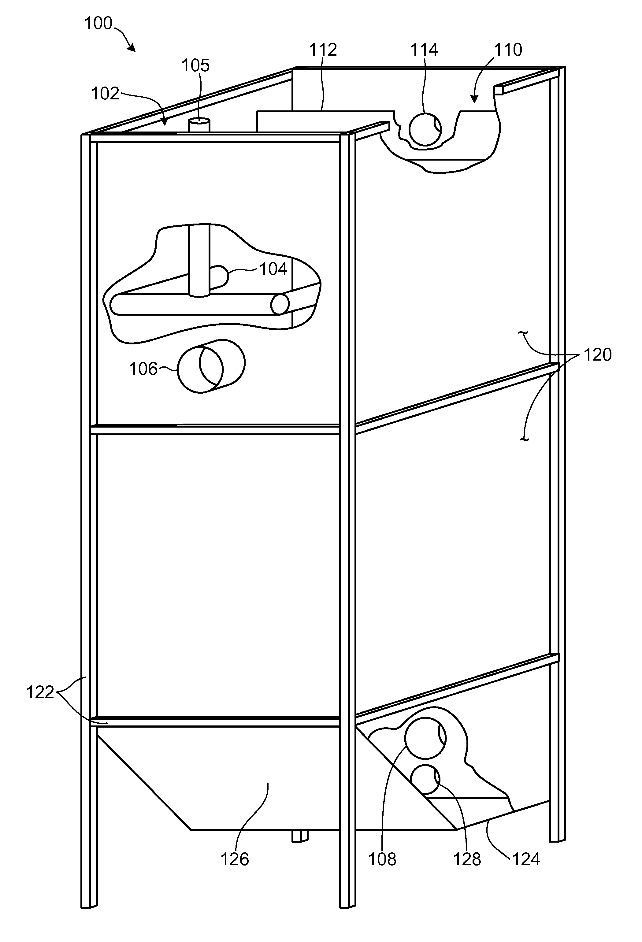
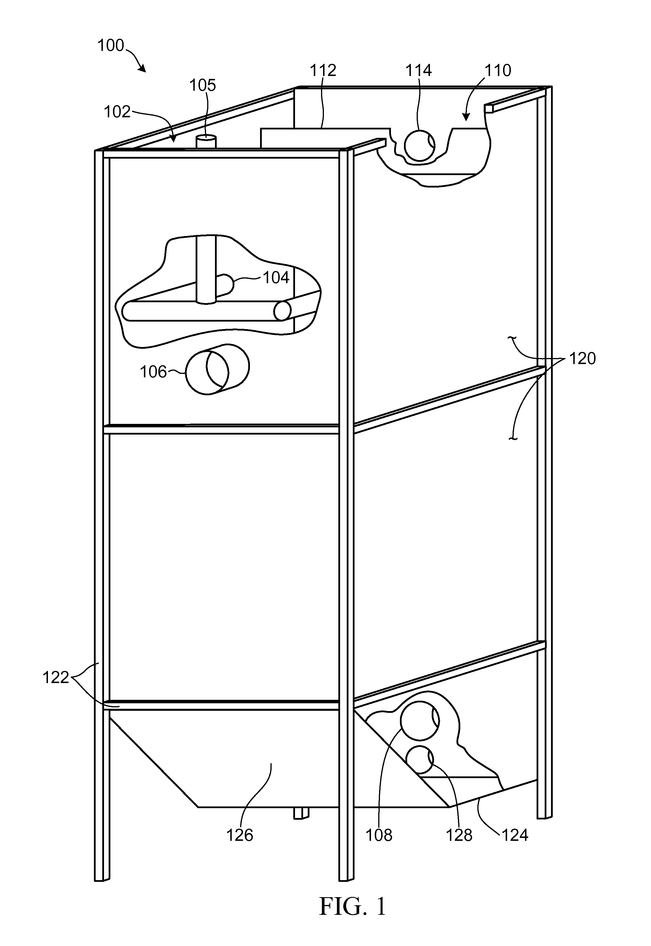
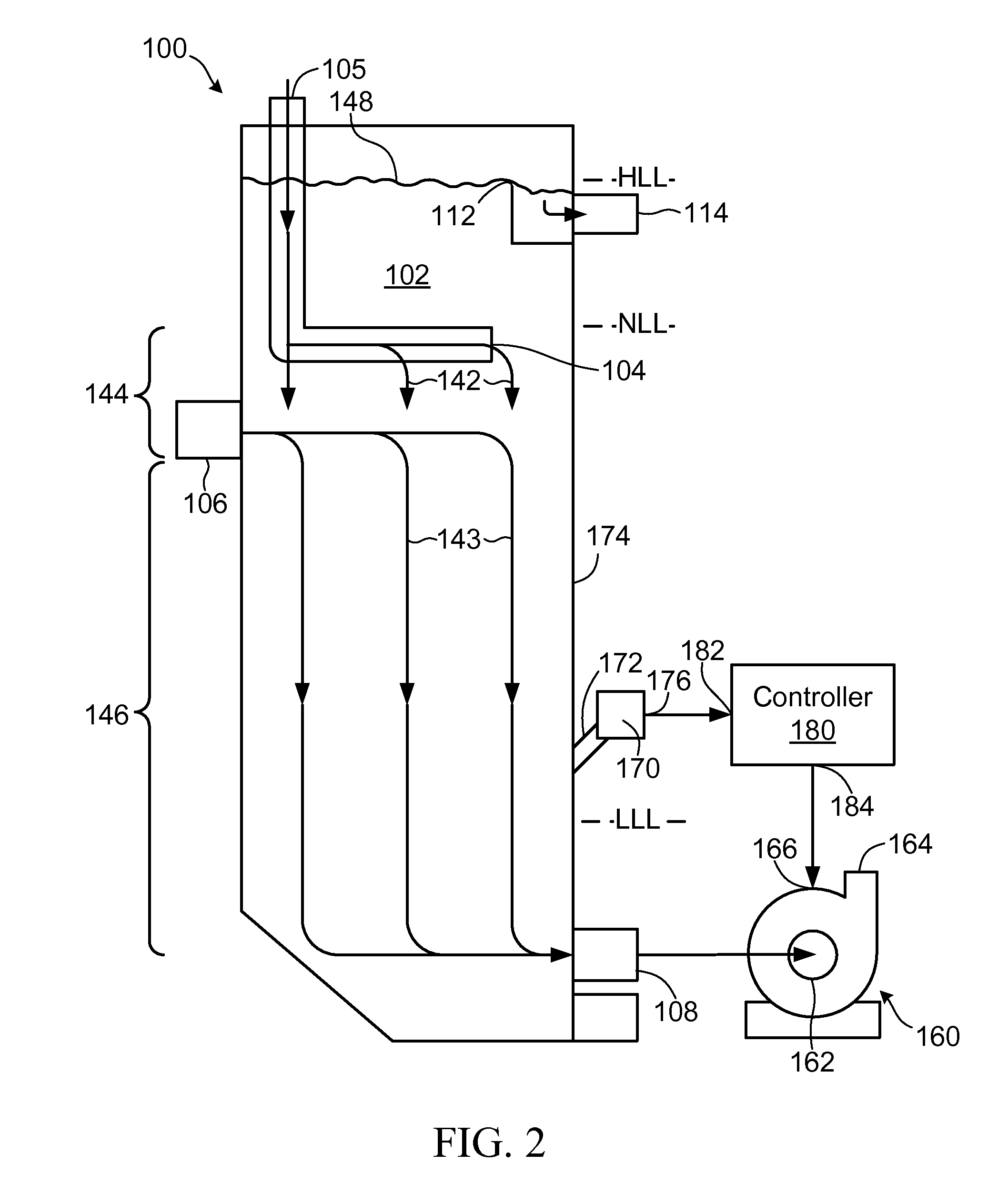
[0049]Referring to FIG. 1, a pumpbox apparatus according to a first embodiment of the invention is shown generally at 100. The pumpbox apparatus 100 includes a reservoir volume 102 having a first inlet 104 for receiving a feedstock stream and a second inlet 106 for receiving a water stream. The reservoir volume 102 is in communication with a discharge outlet 108 disposed to discharge accumulated liquid from the reservoir volume. The reservoir volume 102 is operable to accumulate the feedstock stream received at the first inlet 104 and the water stream received at the second inlet 106 to a first liquid level in the reservoir volume while withdrawing a discharge stream through the discharge outlet 108 to cause a flow of liquid through the pumpbox apparatus 100. In one embodiment the density of the discharge stream may be between about 122×101 and about 128×101 kg / m3.

[0050]The first inlet 104 is located above the second inlet 106. In this embodiment the first inlet 104 is in communicat...


PUM

PropertyMeasurementUnit
densityaaaaaaaaaa
densityaaaaaaaaaa
flow velocityaaaaaaaaaa

Abstract

A pumpbox apparatus includes a reservoir volume having a first inlet for receiving a feedstock stream and a second inlet for receiving a water stream, the reservoir volume being in communication with a discharge outlet disposed to discharge accumulated liquid from the reservoir volume. The reservoir volume is operable to accumulate the feedstock stream and the water stream in the reservoir volume while withdrawing a discharge stream through the discharge outlet to cause a flow of liquid through the pumpbox. The first inlet defines a first flow velocity region between the first inlet and the second inlet and a second flow velocity region between the second inlet and the discharge outlet. The first flow velocity is lower than the second flow velocity to facilitate flotation of a low specific gravity portion of the feedstock through the first region toward an upper surface of the liquid accumulated in the reservoir volume.

Description

BACKGROUND OF THE INVENTION[0001]1. Field of Invention[0002]This invention relates generally to processing of a feedstock and more particularly to a pumpbox for receiving a hydrocarbon feedstock.[0003]2. Description of Related Art[0004]Hydrocarbon feedstocks are generally viscous and may be entrained with other components such as rock, sand, clay and other minerals. As a result, such feedstocks require processing to separate useful hydrocarbon products from residue before transport and refining.[0005]One example of a hydrocarbon ore deposit is the Northern Alberta oil sands, which comprises about 70 to about 90 percent by weight of mineral solids including sand and clay, about 1 to about 10 percent by weight of water, and a bitumen or oil film. The bitumen may be present in amounts ranging from a trace amount up to as much as 20 percent by weight. Due to the highly viscous nature of bitumen, when excavated some of the ore may remain as clumps of oversize ore that requires sizing to ...

Claims


Application Information

Patent Timeline
Patent Type & Authority Patents(United States)
IPC IPC(8): B03B1/00B03B5/62C02F1/24B01D21/24B03B9/02B03D1/02B03D1/14B03D1/24
CPCB03D1/247B03D1/028B03D1/1456B03D1/1468B03D1/1493B03D2203/006
Inventor HANN, THOMAS CHARLESGARNER, WILLIAM NICHOLAS
Owner SUNCOR ENERGY INC
Why Eureka
Try Eureka