A kitchen waste recycling device

A technology for processing equipment and kitchen waste, applied in transportation and packaging, chemical instruments and methods, solid waste removal, etc., can solve the problems of increasing equipment cost and use cost, cumbersome operation, increasing failure points, etc., and achieve resource improvement. Recycling rate, labor saving, odor reduction effect

Active Publication Date: 2021-10-22
北京申城生物科技集团有限公司
View PDF9 Cites 0 Cited by
  • Summary
  • Abstract
  • Description
  • Claims
  • Application Information

AI Technical Summary

Problems solved by technology

[0003] However, there are still obvious defects in its use: 1. The above-mentioned device cannot separate the liquid and solid in the kitchen waste, let alone realize the separation of oil and water, and cannot classify, recycle and reuse resources. Therefore, its use effect is very limited; 2. The above-mentioned device cannot sterilize kitchen waste, not only will it produce a large odor when the garbage is fermented, but also the final organic solids produced may also exist due to incomplete sterilization Potential safety hazard; 3. The above-mentioned device cannot automatically introduce an appropriate amount of starter while introducing solid kitchen waste, and the operation is cumbersome, and the addition of nano-biochemical liquid as a starter in the above-mentioned device is carried out after crushing the garbage. It is easy to have the disadvantages of uneven addition of fermentation agent and inability to fully mix with crushed garbage; 4. The addition of degradable solid agents in the above-mentioned device needs to rely on the auger motor to drive the operation. On the whole, there are many electrical equipment used in the above-mentioned device , it will not only increase the device cost and use cost, but also increase the failure points, which is not convenient for replacement and maintenance, and is not convenient for mass promotion and use

Method used


Image

  • A kitchen waste recycling device
  • A kitchen waste recycling device
  • A kitchen waste recycling device

Examples


Embodiment Construction

[0031] The following will clearly and completely describe the technical solutions in the embodiments of the present invention with reference to the accompanying drawings in the embodiments of the present invention. Obviously, the described embodiments are only some, not all, embodiments of the present invention. Based on the embodiments of the present invention, all other embodiments obtained by persons of ordinary skill in the art without making creative efforts belong to the protection scope of the present invention.

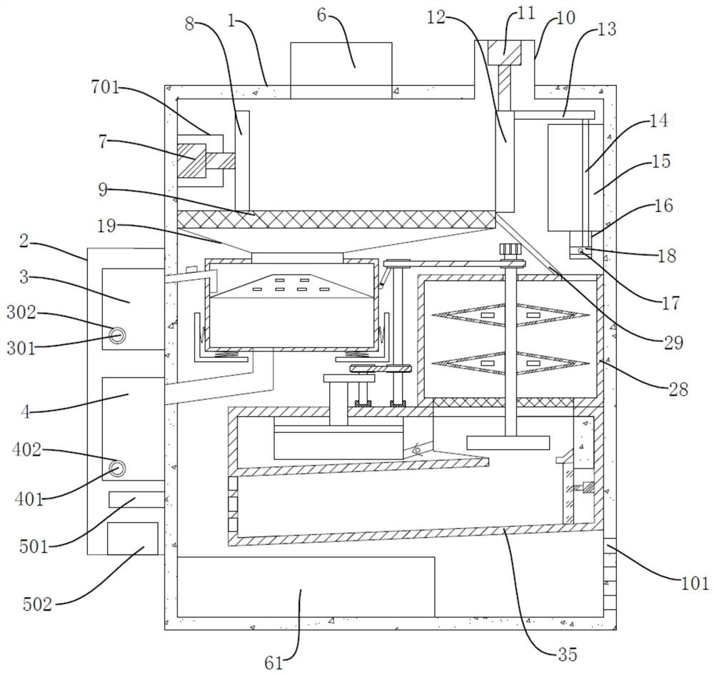
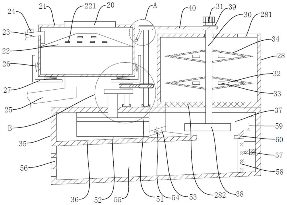
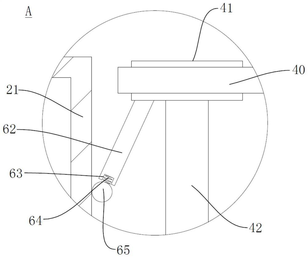
[0032] see Figure 1-4 , the present invention provides a technical solution:

[0033] A kitchen waste recycling treatment device, comprising a box body 1, a side frame 2 is fixedly arranged on the outer wall of the box body 1, and an oil collection tank 3, a water collection box 4, a processor 501 and a control panel 502 are fixedly arranged in the side frame 2 The opening and closing of the first hydraulic cylinder 7, the second hydraulic cylinder 11, the oil...


PUM


Abstract

The invention discloses a kitchen waste recycling treatment device, which includes a box body, an oil collecting tank, a water collecting tank, a processor and a control panel are fixedly arranged in the side frame, and the output end of the second hydraulic cylinder is fixedly arranged with The baffle plate, the push rod is fixedly connected to the non-center of the circular blocking plate; the inner cavity of the oil-water separation box is fixed with an oil collecting plate; the inner cavity of the box body is fixed with a crushing box, An ultraviolet lamp tube is embedded in the transparent cone, and a metal cutting edge is fixedly arranged on the edge of the transparent cone; Multiple extrusion holes are opened on the side wall. The invention provides a kitchen waste recycling treatment device, which can perform solid-liquid separation first, and then oil-water separation, and has a better flotation effect. During use, it can be linked to realize the addition of leavening agent and curing agent, saving manual operations and concentrating functions. , the structure is streamlined, and it is worth promoting.

Description

technical field [0001] The invention relates to the technical field of garbage treatment, in particular to a kitchen waste recycling treatment device. Background technique [0002] In the prior art, the application number is "201911326508.X", which is a kind of kitchen waste disposer for processing kitchen waste. A crushing device, a fermentation filtering device and a particle forming device are sequentially arranged in the casing from top to bottom; the crushing device includes The crushing seat fixed on the inner wall of the casing has a material inlet on the top; the crushing shaft of the crushing motor extends into the hollow part of the crushing seat, and a crushing disc with multiple crushing teeth is set on the crushing shaft, which is set on the inner wall of the crushing seat. With corresponding fixed teeth, the kitchen waste disposer puts the kitchen organic waste into the crushing device for crushing, passes through the fermentation reaction of the fermentation a...

Claims


Application Information

Patent Timeline
Patent Type & Authority Patents(China)
IPC IPC(8): B09B3/00B09B5/00
CPCB09B3/00B09B5/00B09B2101/02
Inventor 杨强强程静静
Owner 北京申城生物科技集团有限公司
Why Eureka
Try Eureka