Light-emitting device with vignetting effect

a technology of light-emitting devices and vignetting, which is applied in the direction of color television details, light fastenings, optical signalling, etc., can solve the problems of increased manufacturing costs, poor yield rate, and user discomfort of light-emitting diodes, so as to reduce the brightness of light-emitting, improve disadvantage, and high cost

Active Publication Date: 2015-03-10
WISTRON CORP
View PDF1 Cites 3 Cited by
  • Summary
  • Abstract
  • Description
  • Claims
  • Application Information

AI Technical Summary

Benefits of technology

[0017]According to the disclosure, the decoration plate further comprises a translucent layer disposed inside the guiding hole corresponding to the mesh layer, and the translucent layer is for blocking the light derived from the light source partially, so as to generate a nebulization effect.
[0021]The present invention provides the light-emitting device with vignetting effect. The light derived from the light source can be divided into the parallel direct light, the oblique light and the scattering light by the first light guiding tunnel and the second light guiding tunnel formed in the light guiding structure, so as to generate the vignetting effect. Furthermore, it can reduce the brightness of the light emitting outside the light-emitting device to comfort the user's eyes by the opaque layer of the decoration plate. In addition, it can design that the diameter of the guiding hole is less than the diameter of the second opening of the second light guiding tunnel or additionally dispose the translucent layer to shade the contour of the light source. Therefore, the present invention improves a disadvantage of high cost and a poor yield rate because it has to shade the light source by means of the light guiding column, painting or plating shading material in the prior art. In addition, the present invention provides a freedom to design the light-emitting device with a beautiful appearance.

Problems solved by technology

However, it increases the manufacturing cost and spends much time in postprocessing, resulting in a poor yield rate.
A conventional method for adjusting the brightness of the light source is using a variable resistor, but an adjustable range of the brightness by the conventional method is limited, so that the light-emitting diode makes a user feel uncomfortable due to the strong brightness as the user sees the functional indicator.
As a result, it is an important issue to design a light-emitting device which can not only shade the contour of the light source but also provide a comfortable brightness of the light source without additional manufacturing cost.

Method used


Image

  • Light-emitting device with vignetting effect
  • Light-emitting device with vignetting effect
  • Light-emitting device with vignetting effect

Examples


Embodiment Construction

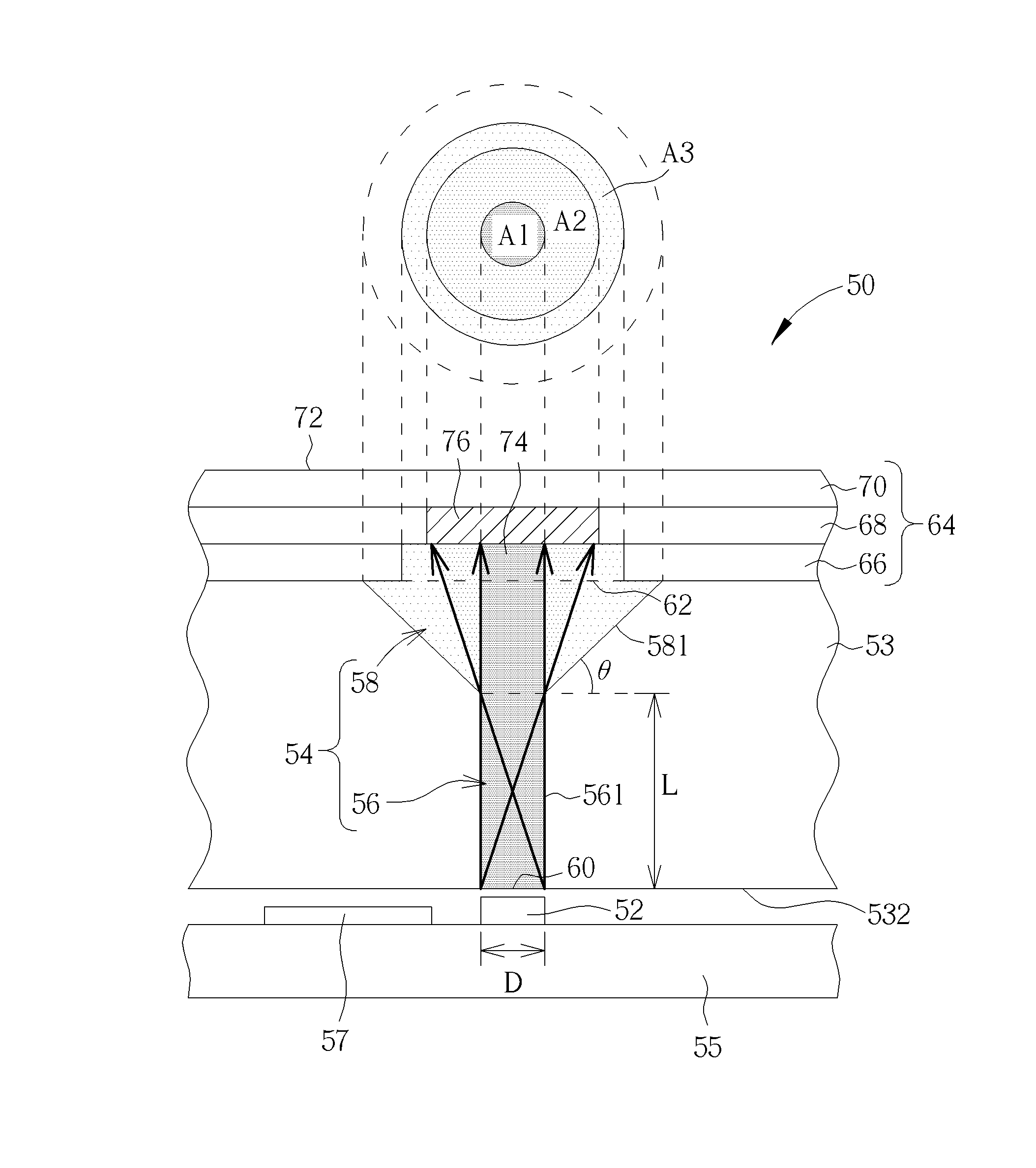
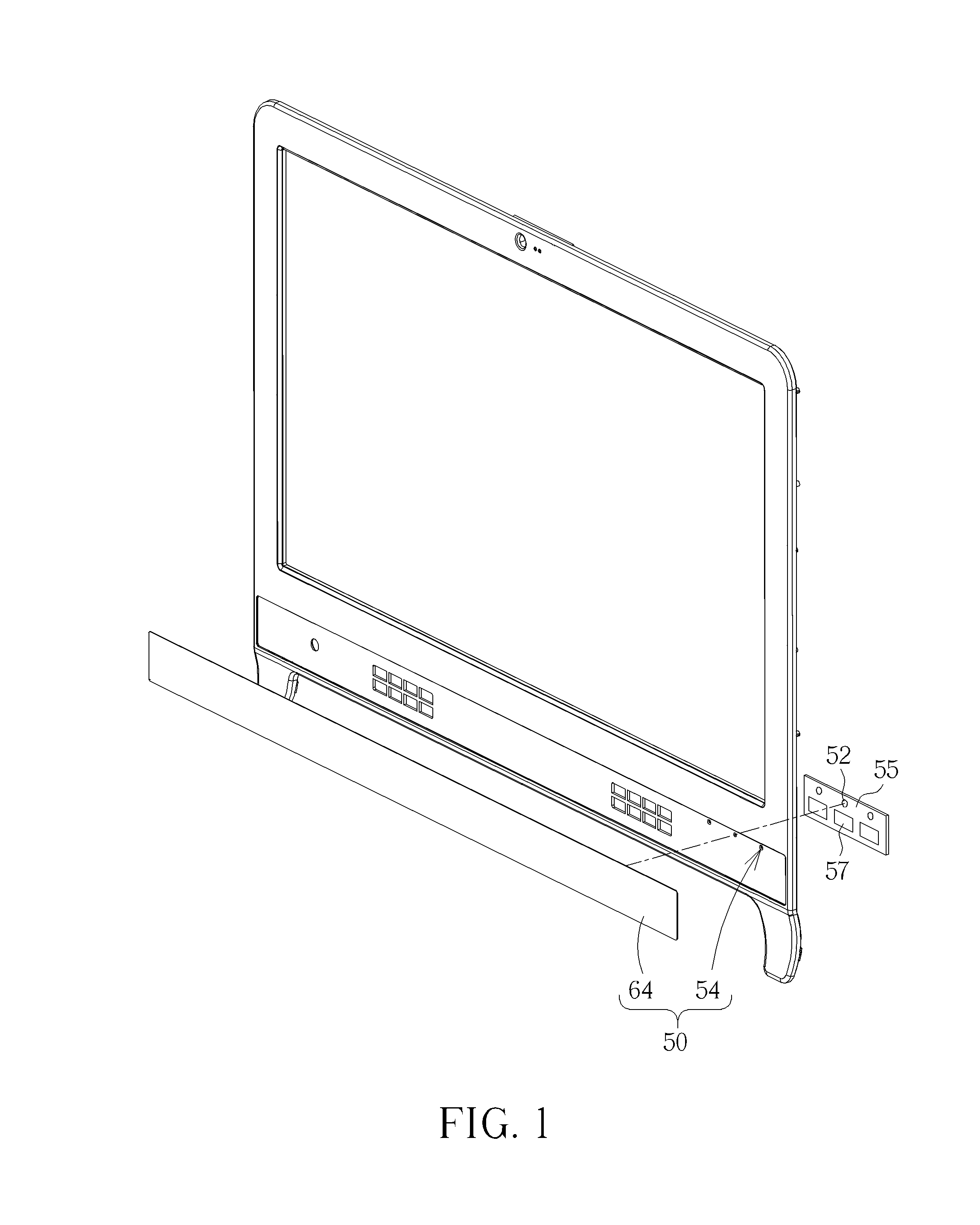
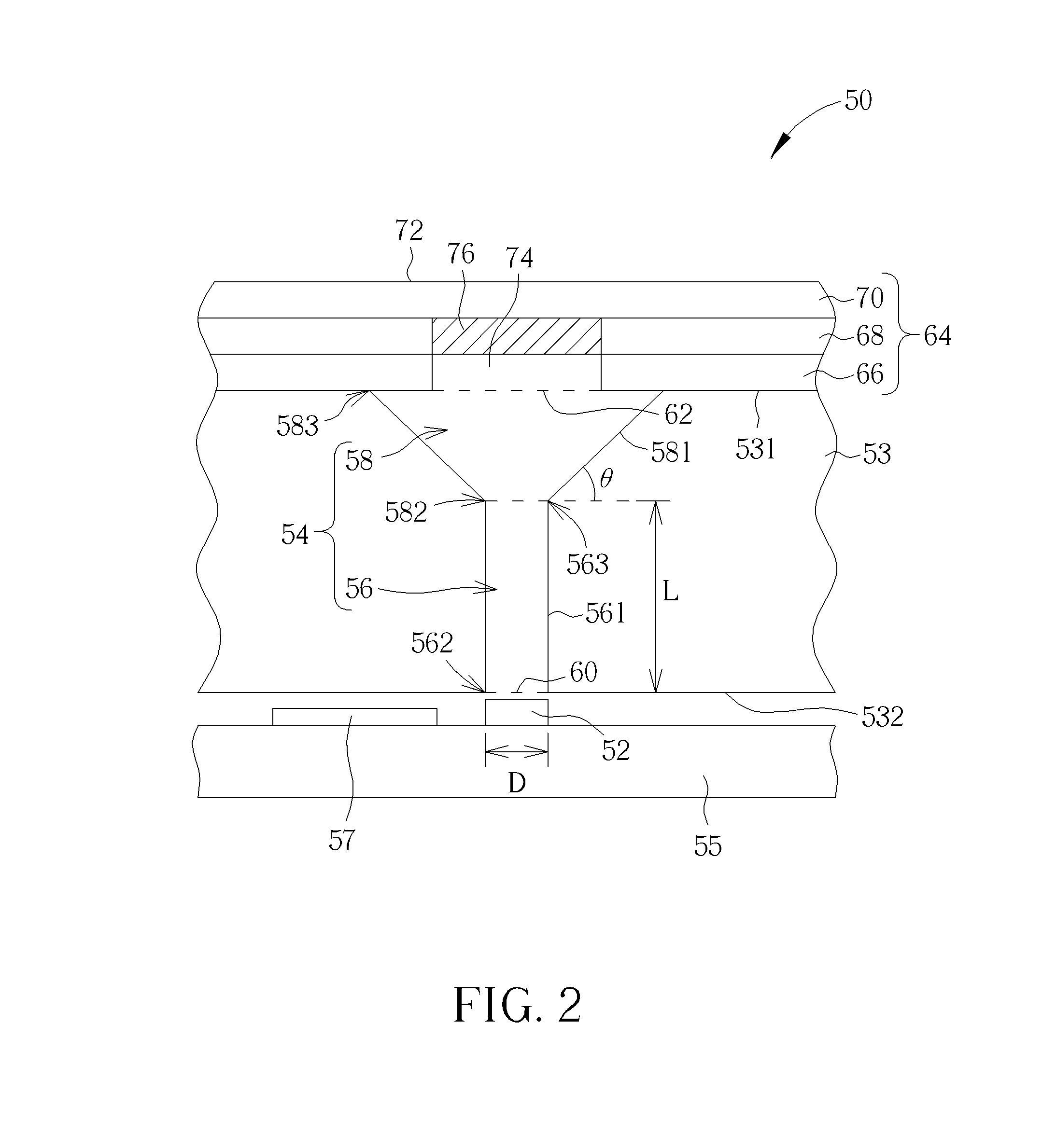
[0028]Please refer to FIG. 1 and FIG. 2. FIG. 1 is diagram of a light-emitting device 50 installed on an electronic device according to an embodiment of the present invention. FIG. 2 is a sectional view of the light-emitting device 50 according to the embodiment of the present invention. The light-emitting device 50 can be a functional indicator installed on an All-In-One PC, a liquid crystal display (LCD) device, a LCD TV, and so on. The light-emitting device 50 includes a light source 52, a panel 53 and a light guiding structure 54. The light source 52 is for emitting light and can be a light-emitting diode installed on a circuit board 55. The light-emitting device 50 can further include a touch sensing component 57 disposed on the circuit board 55 and close to the light source 52. The touch sensing component 57 can be a capacitive-type or a resistive-type sensing component. The panel 53 can be a front bezel of the electronic device and can be made of opaque material. The panel 53...


PUM


Abstract

A light-emitting device includes a light source, a panel and a light guiding structure. The light guiding structure includes a first light guiding tunnel and a second light guiding tunnel. The first light guiding tunnel includes a first end and a second end. A first opening is formed at the first end and close to the light source. The second light guiding tunnel includes a first end and a second end. The first end of the second light guiding tunnel communicates with the second end of the first light guiding tunnel. A diameter of the second end of the second light guiding tunnel is greater than a diameter of the first end of the second light guiding tunnel. A second opening is formed at the second end of the second light guiding tunnel. A diameter of the second opening is greater than a diameter of the first opening.

Description

BACKGROUND OF THE INVENTION[0001]1. Field of the Invention[0002]The present invention relates to a light-emitting device, and more specifically, to a light-emitting device capable of shading a contour of a light source and generating a vignetting effect by a structural design.[0003]2. Description of the Prior Art[0004]In popular display devices, such as an All-In-One PC, a liquid crystal display (LCD) monitor and a LCD TV, a functional indicator is often implemented by a light-emitting diode. Because the appearance of the conventional electronic device tends to be simple, the functional indicator is often implemented by shading a contour of a light source. A guiding column is used to sheathe the functional indicator on the light-emitting diode, and the light source is shaded by painting or plating around an opening of the light source, so as to shade the contour of the light source. However, it increases the manufacturing cost and spends much time in postprocessing, resulting in a p...

Claims


Application Information

Patent Timeline
Patent Type & Authority Patents(United States)
IPC IPC(8): F21V7/04H01L33/00F21V8/00F21V33/00G09G3/20H04N5/64
CPCG02B6/0096F21V33/0052G02B6/0008G09G3/2092H04N5/64G06F1/1601
Inventor CHEN, KUANG-WENHUANG, YU-HSINCHEN, FU-CHIENLAI, CHUN-CHIANG
Owner WISTRON CORP
Why Eureka
Try Eureka