
Tamping device with synchronizing device and method for same

a technology of synchronizing device and tamper, which is applied in the field of vibration tamper, can solve the problems of reducing the permitted use period of the apparatus, putting the operator under considerable stress, and reducing the guidability of the tamper, so as to relieve the stress on the operator and expand the use range of the tamper

Inactive Publication Date: 2015-03-10
WACKER NEUSON SE
View PDF15 Cites 0 Cited by
  • Summary
  • Abstract
  • Description
  • Claims
  • Application Information

AI Technical Summary

Benefits of technology

The invention is about a tamping device that can prevent the synchronous operation of the device from being lost or taken away. This will expand the usage range of the tamper and make it easier for the operator to guide the tamper with less stress.

Problems solved by technology

In the event of an asynchronous operation of this type, the passive system (upper mass, gripping frame for the operator) reacts with high amplitudes, which makes the guidability of the tamper more difficult.
In addition, the operator is put under considerable stress by the guiding of the tamper, wherein the hand-arm accelerations reach increased values and, as a result, reduce the permitted use period of the apparatus.
In addition, the tamper operates at weak power and therefore the soil can scarcely still be compacted.
Furthermore, the mechanical system is highly stressed by the high movement amplitudes of the upper mass that occur during the asynchronous operation, which may result in the mechanical assemblies being overloaded and in the apparatus failing.
This non-uniform behavior of a tamper on different soils becomes all the more serious, the more power it is possible for the apparatuses to output into the soil.
On the other hand, however, the usable compaction power of the machine is also limited as a result because—given appropriately compactable soils—the entire power capacity of the tamper cannot be utilized.

Method used


Image

  • Tamping device with synchronizing device and method for same
  • Tamping device with synchronizing device and method for same
  • Tamping device with synchronizing device and method for same

Examples


Embodiment Construction

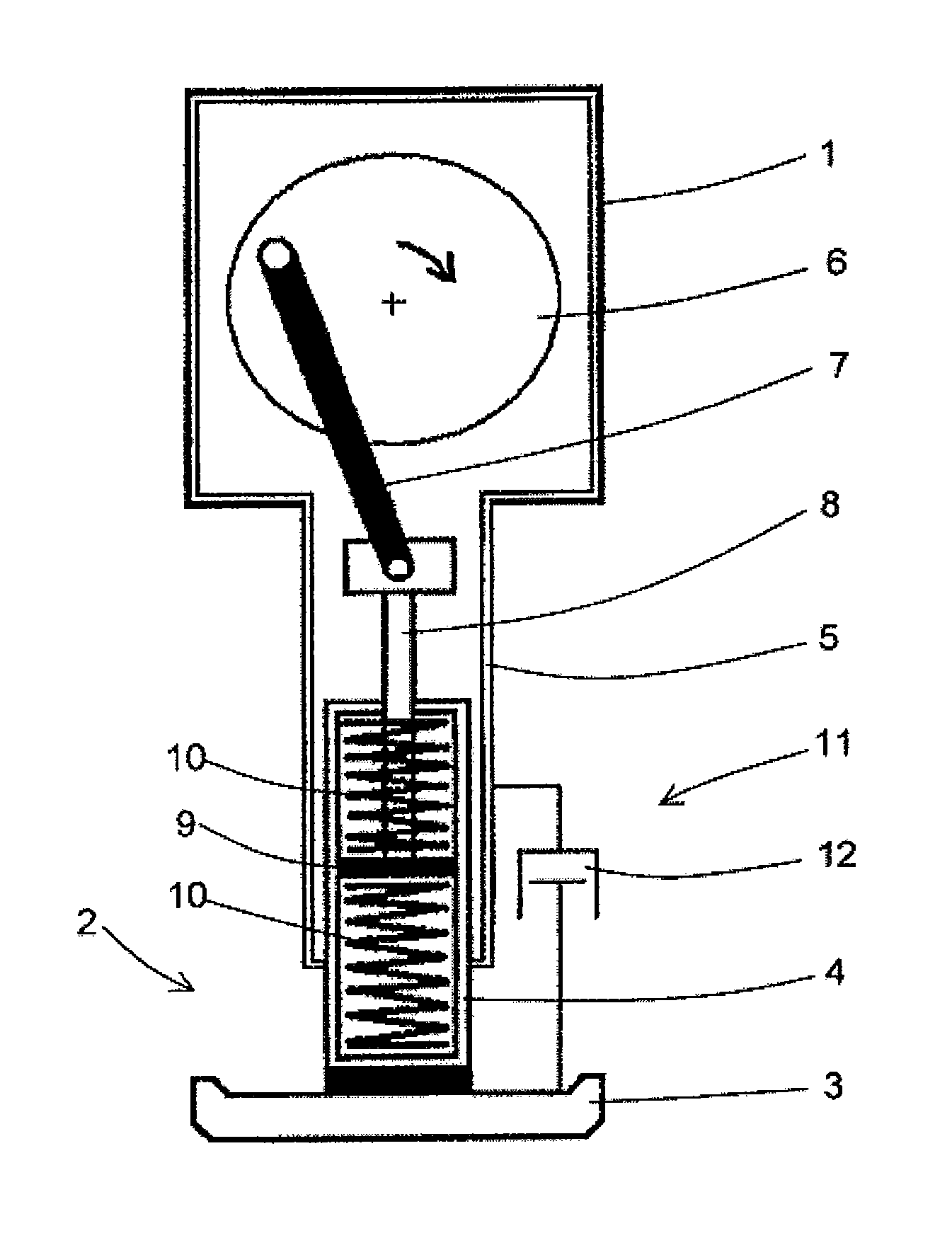
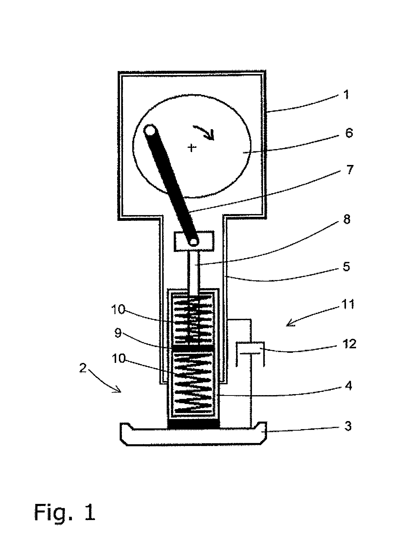
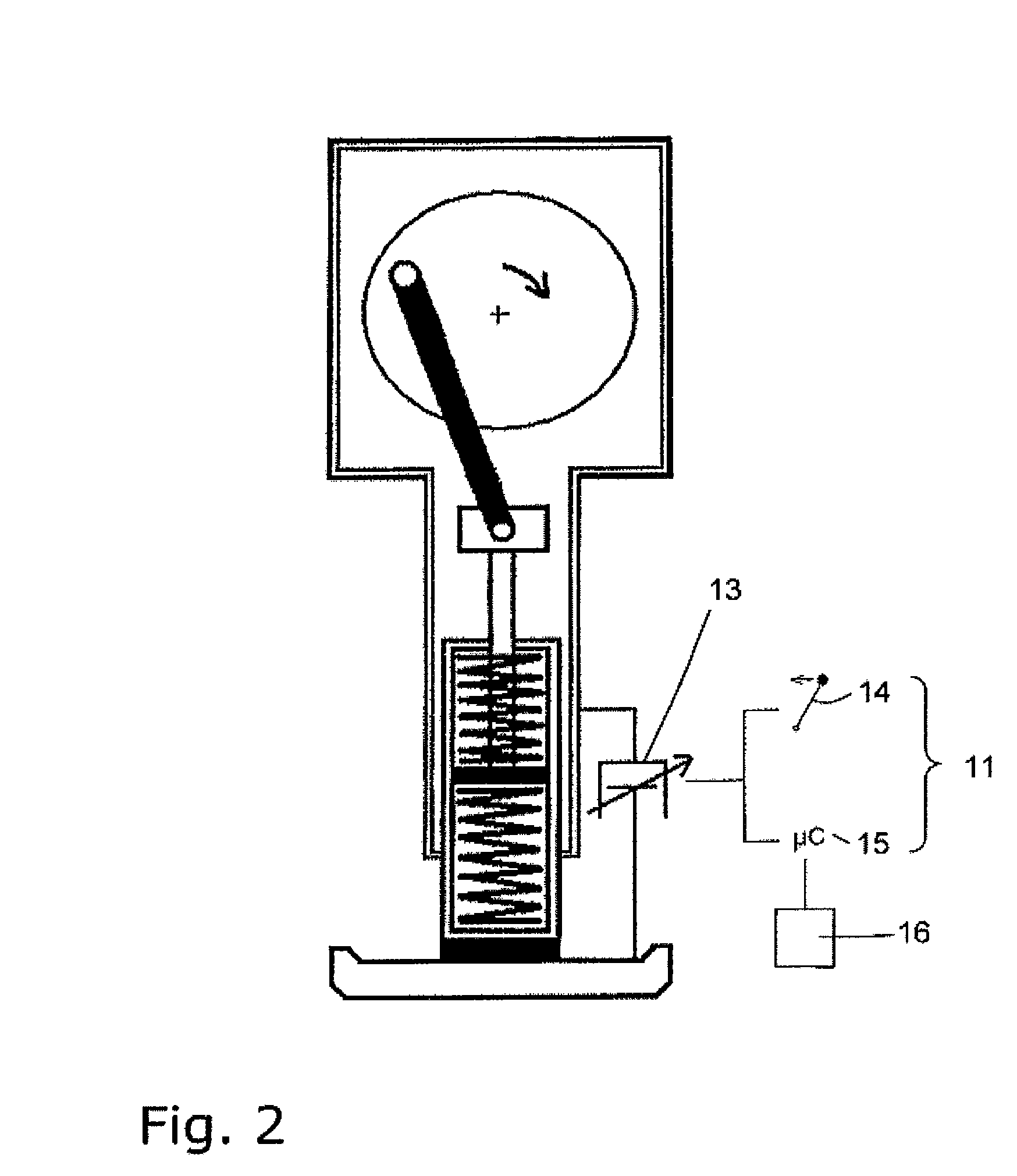
[0049]FIG. 1 shows a tamping device (a tamper) for soil compaction. A tamping device of this type, which is also referred to as a vibrating tamper, has an upper mass 1 on which a driver (not illustrated), for example an electric motor or an internal combustion engine, is provided. A guide bracket or a guide frame (likewise not illustrated), with the aid of which an operator can guide and hold the tamper, can be fastened to the upper mass 1.

[0050]A lower mass 2, which in particular includes a tamping foot with a soil contact element 3, is provided below the upper mass 1. A guide tube 4 which likewise belongs to the lower mass 2 or to the tamping foot and is movable linearly to and fro in a guide tube 5 of the upper mass 1 is formed above the soil contact element 3.

[0051]The tamping movement of the lower mass 2 is produced on the basis of the movement of the latter to and fro with the aid of a tamping system (vibration-exciting device). For this purpose, a crank drive 6 which is drive...


PUM


Abstract

A tamping device for soil compaction having an upper mass with a drive and a lower mass that can be moved relative to the upper mass with a soil contacting element. In order to cause a working movement of the soil contacting element, a vibration generating device is provided. In addition to the vibration generating device, a manipulating device, for example in the form of a damping body, is provided in an operatively connected manner between the upper mass and the lower mass. The damping properties of the damping body can be modifiable.

Description

BACKGROUND OF THE INVENTION[0001]1. Field of the Invention[0002]The invention relates to a tamping device for soil compaction, in particular to a vibrating tamper.[0003]2. Discussion of the Related Art[0004]A tamper customarily comprises an upper mass having a drive and a lower mass which has a soil contact element and is movable relative to the upper mass. A tamping system (vibration-exciting device) which is drivable by the drive acts between the upper mass and the lower mass and can be used to bring about the working movement of the soil contact element. Tampers of this type are an indispensable aid on building sites. The function thereof is dependent on energy sources (a combustion drive or electric motor drive) and on countersinking (of the contact element with respect to the soil) and on the mechanical structures of the tamping system, such as, for example, the mass ratios of the moving and non-moving parts, the transmission ratios, the springs (steel or pneumatic), the damper...

Claims


Application Information

Patent Timeline
Patent Type & Authority Patents(United States)
IPC IPC(8): E02D3/068E02D3/046
CPCE02D3/068E02D3/046
Inventor STEFFEN, MICHAEL
Owner WACKER NEUSON SE
Learn More