
Boom assembly

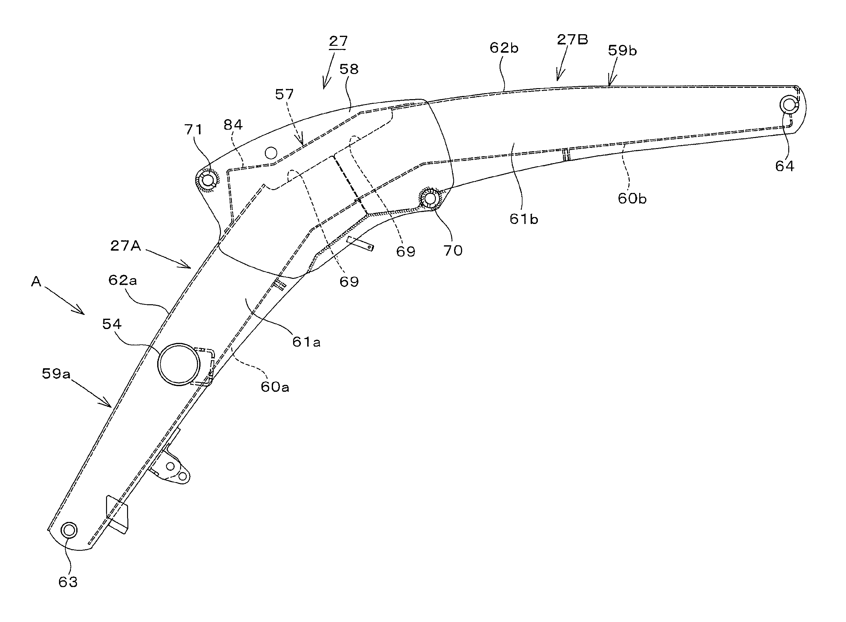
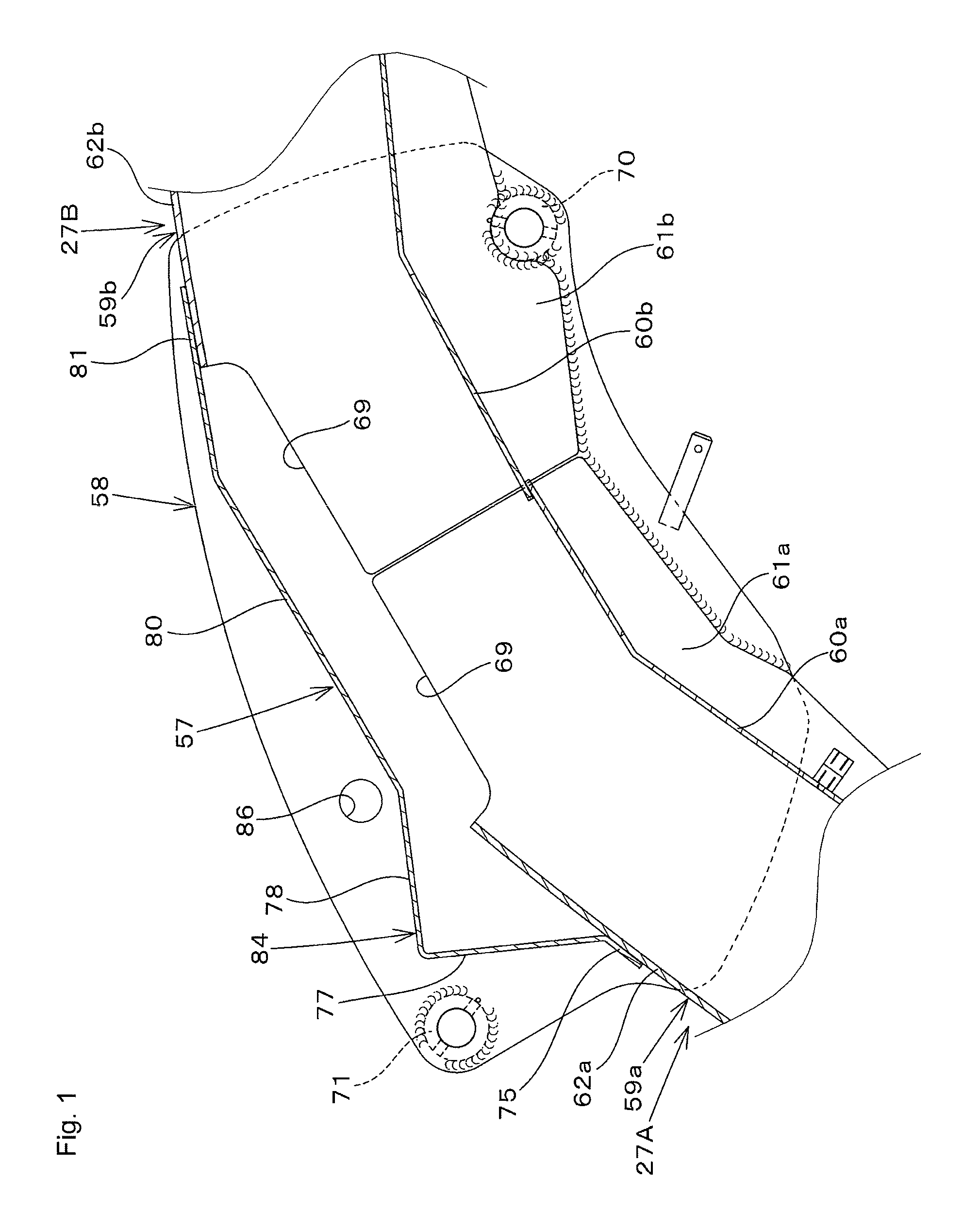
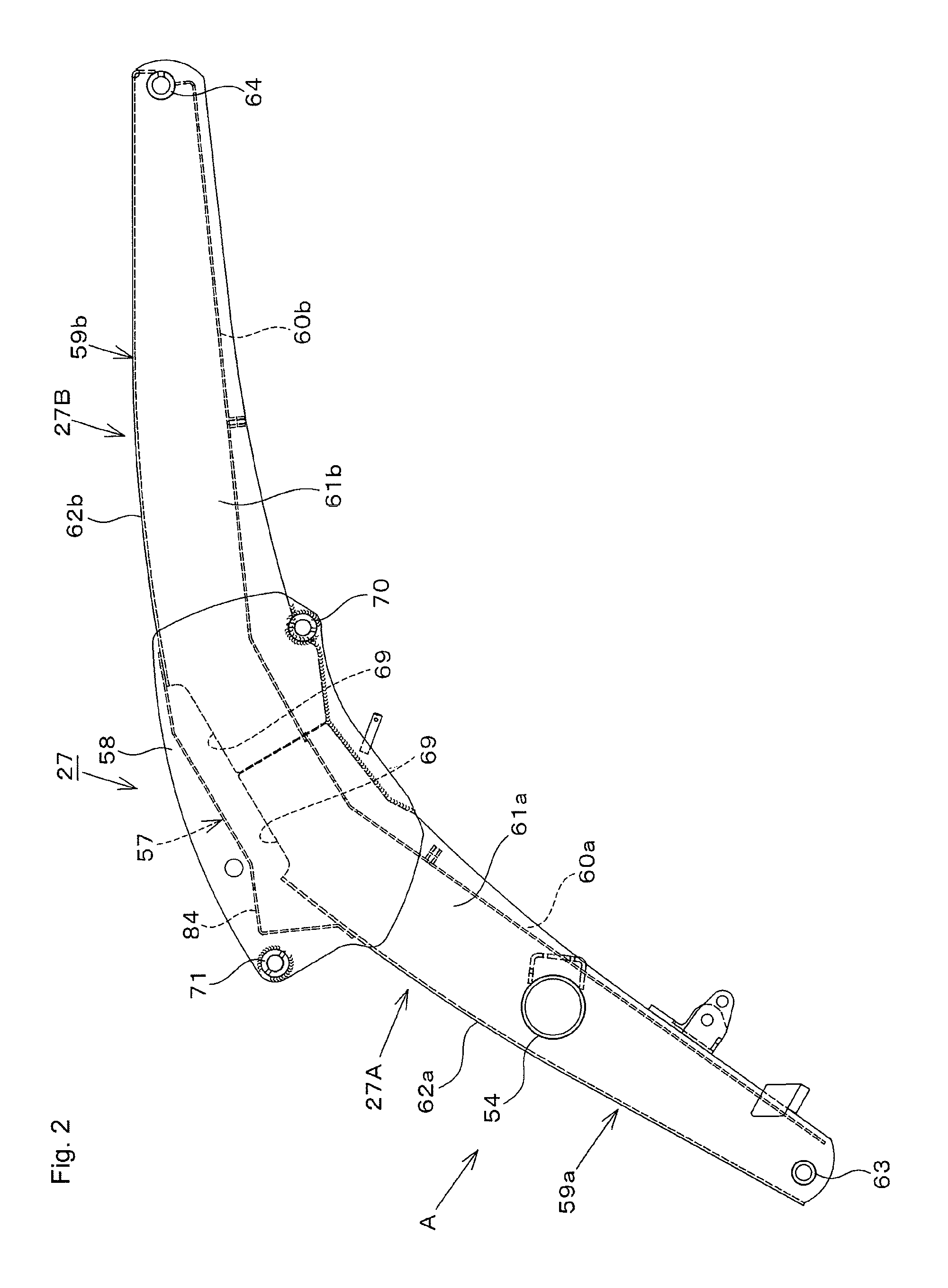
a boom assembly and boom technology, applied in the field of boom assembly, can solve the problems of increased weight of the boom assembly and increased cost, and achieve the effects of reducing costs, reducing costs, and improving strength in the area around the pivoting support 71 for the working tool cylinder

Active Publication Date: 2015-03-10
KUBOTA CORP
View PDF5 Cites 4 Cited by
  • Summary
  • Abstract
  • Description
  • Claims
  • Application Information

AI Technical Summary

Benefits of technology

This design effectively enhances the strength around the pivoting support, reduces material usage, and improves the external appearance by allowing for a lighter and cheaper boom assembly without compromising structural rigidity or appearance.

Problems solved by technology

Accordingly, due to the left and right side plates being thick in the conventional method, costs have increased and the weight of the boom assembly has increased.

Method used


Image

  • Boom assembly
  • Boom assembly
  • Boom assembly

Examples


Embodiment Construction

[0018]The particulars shown herein are by way of example and for purposes of illustrative discussion of the embodiments of the present invention only and are presented in the cause of providing what is believed to be the most useful and readily understood description of the principles and conceptual aspects of the present invention. In this regard, no attempt is made to show structural details of the present invention in more detail than is necessary for the fundamental understanding of the present invention, the description is taken with the drawings making apparent to those skilled in the art how the forms of the present invention may be embodied in practice.

[0019]Hereinafter, exemplary embodiments of the present invention are described with reference to the drawings. In FIG. 4, 1 is a tractor (moving vehicle) and 2 is a front loader (loader) detachably mounted to a front portion of the tractor 1. The tractor 1 includes a left-right pair of front wheels 3 and a left-right pair of ...


PUM


Abstract

A boom has a central connection plate attached between a pair of side plates, and a rear portion side of a cover plate on a front boom portion and a front portion side of a cover plate on a rear boom portion are connected thereby. A pivoting support for a working tool cylinder used to move a working tool connected to a foremost portion of the front boom portion is provided on a front side of a top portion on each of the left and right side plates. The central connection plate is formed with a connection plate projection projecting from a front portion attached to the rear portion of the cover plate toward a midway portion so as to approach the pivoting support.

Description

CROSS-REFERENCE TO RELATED APPLICATIONS[0001]The present application claims priority under 35 U.S.C. §119 of Japanese Application No. 2011-153842, filed on Jul. 12, 2011, the disclosure of which is expressly incorporated by reference herein in its entirety.BACKGROUND OF THE INVENTION[0002]1. Field of the Invention[0003]The present invention relates to a boom assembly in a working vehicle, such as a front loader.[0004]2. Description of Related Art[0005]In a boom assembly of a front loader, for example, a front boom portion and a rear boom portion are curved at a center portion in a boom's length direction and are connected in a bowed shape protruding on an upper side. A left-right pair of side plates is fixedly positioned on both a left and right side of a rear portion side of the front boom portion and a front portion side of the rear boom portion. A central connection plate is attached between the pair of side plates, and a rear portion side of a cover plate on the front boom porti...

Claims


Application Information

Patent Timeline
Patent Type & Authority Patents(United States)
IPC IPC(8): E02F3/00E02F3/34E02F3/38E02F3/627
CPCE02F3/34E02F3/627E02F3/38
Inventor NISHI, RYOICHI
Owner KUBOTA CORP
Learn More