Ion detector

a detector and ion technology, applied in the field of ion detectors, can solve problems such as improving detection accuracy, and achieve the effects of suppressing the formation of positive electric fields, improving the incidence efficiency of positive ions, and improving the incidence efficiency of negative ions

Active Publication Date: 2015-03-10
HAMAMATSU PHOTONICS KK
View PDF21 Cites 18 Cited by
  • Summary
  • Abstract
  • Description
  • Claims
  • Application Information

AI Technical Summary

Benefits of technology

[0006]Therefore, the present invention is to provide an ion detector which is capable of improving the detection accuracy and also being simplified in structure.
[0032]Where a positive potential is applied to the cover electrode and the electron incident surface and the semiconductor electron detector is an avalanche photodiode, even when, for example, the ion entrance is formed so as to have a sectional shape taking as its longitudinal direction the direction in which the pair of electrode members are opposed, positive ion trajectories to the conversion dynode and negative ion trajectories to the cover electrode and the electron incident surface of the avalanche photodiode can be converged. It is, thereby, possible to improve the incidence efficiency of positive ions in the conversion dynode and the incidence efficiency of negative ions in the cover electrode and the electron incident surface of the avalanche photodiode.

Problems solved by technology

In particular, afterglow that occurs in the process of converting secondary electrons by scintillators (fluorescent materials) has posed a serious problem in improving the detection accuracy.

Method used


Image

  • Ion detector
  • Ion detector
  • Ion detector

Examples


first embodiment

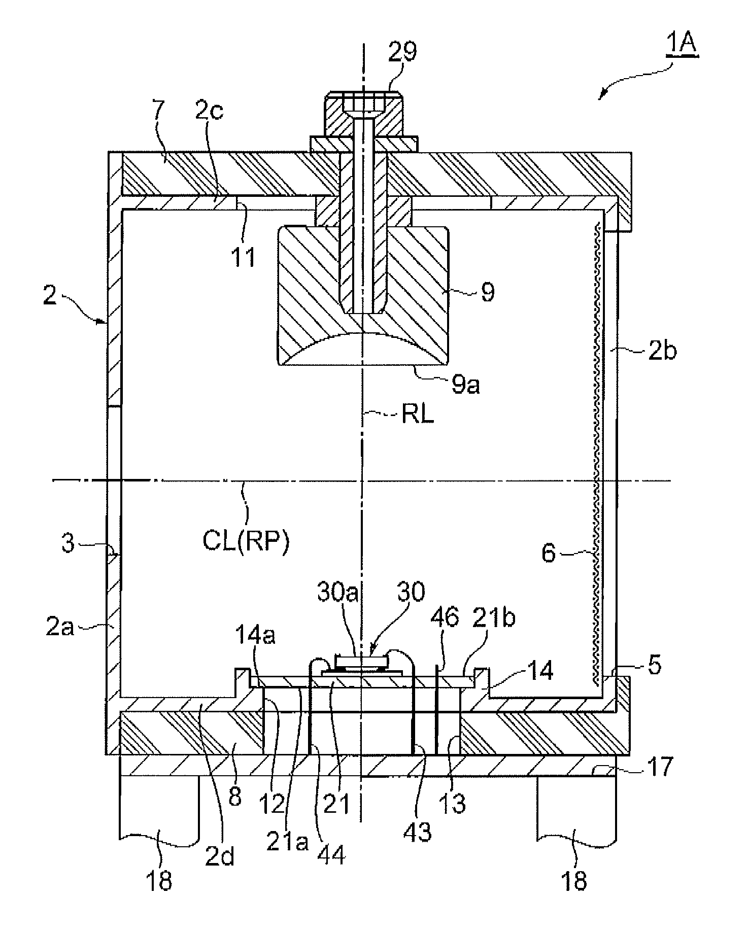
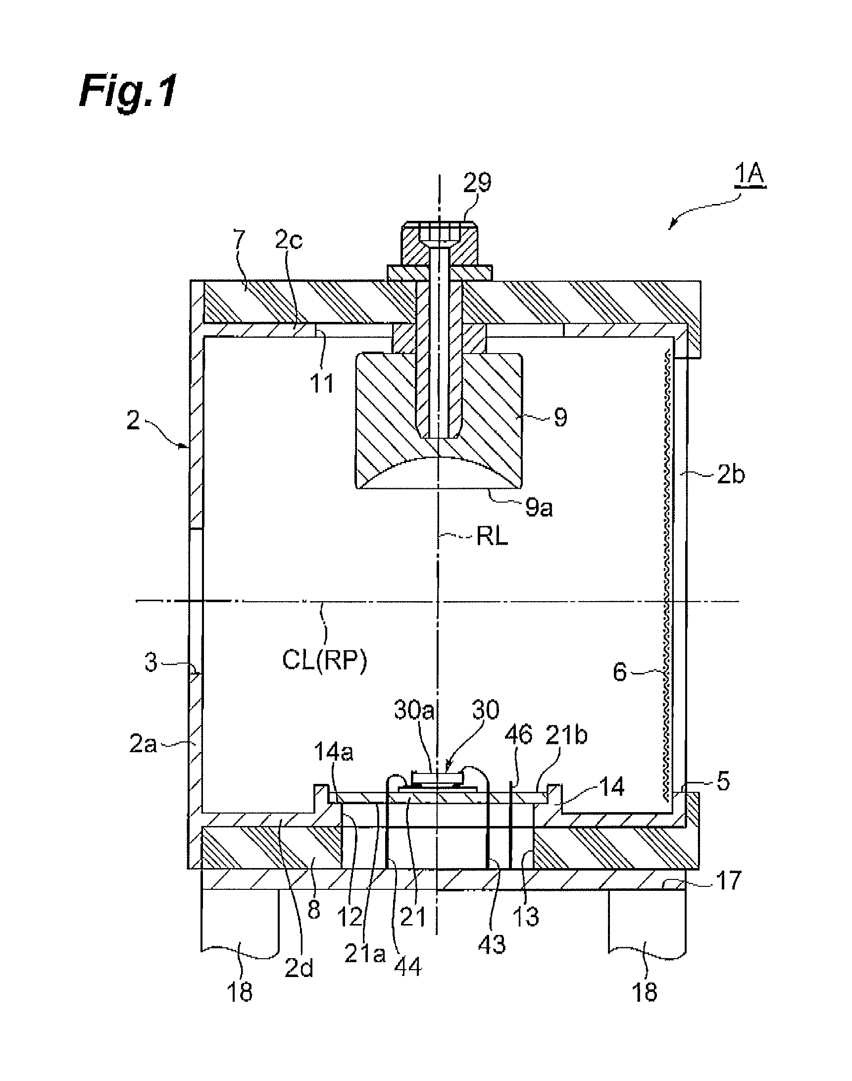
[0049]FIG. 1 is a longitudinal sectional view of the ion detector of the first embodiment of the present invention. FIG. 2 is an enlarged view which shows the ion detector of the first embodiment in a state of being electrically connected to an avalanche photodiode.

[0050]As shown in FIG. 1, an ion detector 1A is provided with a rectangular parallelepiped box-shaped chamber (housing) 2 which is made of SUS 304 (stainless steel). On a side wall 2a of the chamber 2, there is installed an ion entrance 3 having a circular shape in section for allowing positive ions to enter (for example, about 10 mm in diameter). On a side wall 2b of the chamber 2 which is opposed to the side wall 2a, there is installed an opening 5 including the ion entrance 3, when viewed from a direction in which the side wall 2a is opposed to the side wall 2b. At the opening 5, a mesh 6 made of SUS is placed so as to run along an inner surface of the side wall 2b. An insulating member 7 made of a PEEK (polyether ethe...

second embodiment

[0066]Next, a description will be given of the ion detector of the second embodiment. FIG. 3 is a longitudinal sectional view of the ion detector of the second embodiment and that of the third embodiment in the present invention. FIG. 4 is an enlarged view which shows the ion detector of the second embodiment in a state of being electrically connected to an avalanche photodiode.

[0067]An ion detector 1B of the second embodiment is different from the ion detector 1A in that a stem 21 is not directly in contact with a chamber 2 and electrically insulated from the chamber 2 (refer to FIG. 3). Further, the ion detector 1B is different from the ion detector 1A in that a lead pin 44 is electrically connected to the stem 21 (refer to FIG. 4).

[0068]As shown in FIG. 3, the stem 21 is disposed in the chamber 2 of the ion detector 1B. The stem 21 has an external shape which is smaller than a diameter of an opening 12 installed on a bottom wall 2d of the chamber 2 and that of an opening 13 insta...

third embodiment

[0072]Next, a description will be given of the ion detector of the third embodiment. FIG. 5 is an enlarged view which shows the ion detector of the third embodiment which is in a state of being electrically connected to an avalanche photodiode.

[0073]An ion detector 1C of the third embodiment is different from the ion detector 1A in that a stem 21 is electrically insulated from a chamber 2 (refer to FIG. 3). The ion detector 1C is also different from the ion detector 1B in that a lead pin 43 is electrically connected to the stem 21 (refer to FIG. 5).

[0074]The lead pin 43 is directly fixed to the stein 21 and thereby electrically connected to the stem 21. The lead pin 43 is a pin which is connected to a p-electrode 35. Therefore, the stem 21 which is electrically connected to the lead pin 43 becomes equal in potential to the p-electrode.

[0075]According to the ion detector 1C, as with the ion detector 1B of the second embodiment, a potential of the stem 21 is electrically insulated fro...


PUM


Abstract

An ion detector 1A for detecting positive ions is provided with a chamber 2 having an ion entrance 3 which allows positive ions to enter, a conversion dynode 9 which is disposed in the chamber 2 and to which a negative potential is applied, and an avalanche photodiode 30 that is disposed in the chamber 2 and has an electron incident surface 30a which is opposed to the conversion dynode 9 and also into which secondary electrons emitted from the conversion dynode 9 are made incident. The electron incident surface 30a is located closer to the conversion dynode 9 than a positioning part 14 which supports the avalanche photodiode 30 in the grounded chamber 2.

Description

BACKGROUND OF THE INVENTION[0001]1. Field of the Invention[0002]The present invention relates to an ion detector which detects positive ions and also to an ion detector which detects positive ions and negative ions.[0003]2. Related Background Art[0004]Conventional ion detectors including conversion dynodes that emit secondary electrons by ion collisions, scintillators that emit light upon incidence of the secondary electrons emitted from the conversion dynodes, photodetectors that detect the light emitted by the scintillators have been known (refer to, for example, Japanese Patent Application Laid-Open No. H10-188878, Japanese Patent Application Laid-Open No. S63-276862 and Japanese Patent No. 4639379).SUMMARY OF THE INVENTION[0005]Meanwhile, the above-described ion detectors are required to be simplified in structure, in addition to an improvement in detection accuracy. In particular, afterglow that occurs in the process of converting secondary electrons by scintillators (fluoresce...

Claims


Application Information

Patent Timeline
Patent Type & Authority Patents(United States)
IPC IPC(8): G01T1/20G01T1/28
CPCG01T1/28
Inventor KOBAYASHI, HIROSHISUYAMA, MOTOHIROKOTANI, MASAHIROOHMURA, TAKAYUKI
Owner HAMAMATSU PHOTONICS KK
Why Eureka
Try Eureka