
Method for determining the relative position of a first and a second imaging device and devices therefore

a technology of imaging device and relative position, which is applied in the field of camera calibration techniques and devices, can solve the problems of slow and/or inconvenient solution, solution that does not allow camera calibration, and is difficult to support moving cameras while maintaining camera calibration, so as to reduce the necessary processing power

Inactive Publication Date: 2015-03-10
ALCATEL LUCENT SAS
View PDF15 Cites 14 Cited by
  • Summary
  • Abstract
  • Description
  • Claims
  • Application Information

AI Technical Summary

Benefits of technology

This approach enables fast and reliable camera calibration with reduced processing requirements, supporting real-time 3-D information extraction and dynamic camera configurations, without the need for physical calibration objects, and allows for the derivation of 3-D information of moving objects.

Problems solved by technology

Other solutions exist, which do not require such a calibration object; however, these solutions are slow and / or not reliable.
These solutions often have the problem that they comprise a difficult initialization, that they only work on scenes with certain types of features or that they require additional knowledge or information about the scene.
These solutions do not allow camera calibration which is transparent to the end user.
Furthermore it is difficult to support moving cameras while maintaining camera calibration.
State of the art methods do moreover require substantial processing capabilities.
Most of the state of the art technologies do also not allow real time 3-D information extraction.

Method used


Image

  • Method for determining the relative position of a first and a second imaging device and devices therefore
  • Method for determining the relative position of a first and a second imaging device and devices therefore
  • Method for determining the relative position of a first and a second imaging device and devices therefore

Examples


Embodiment Construction

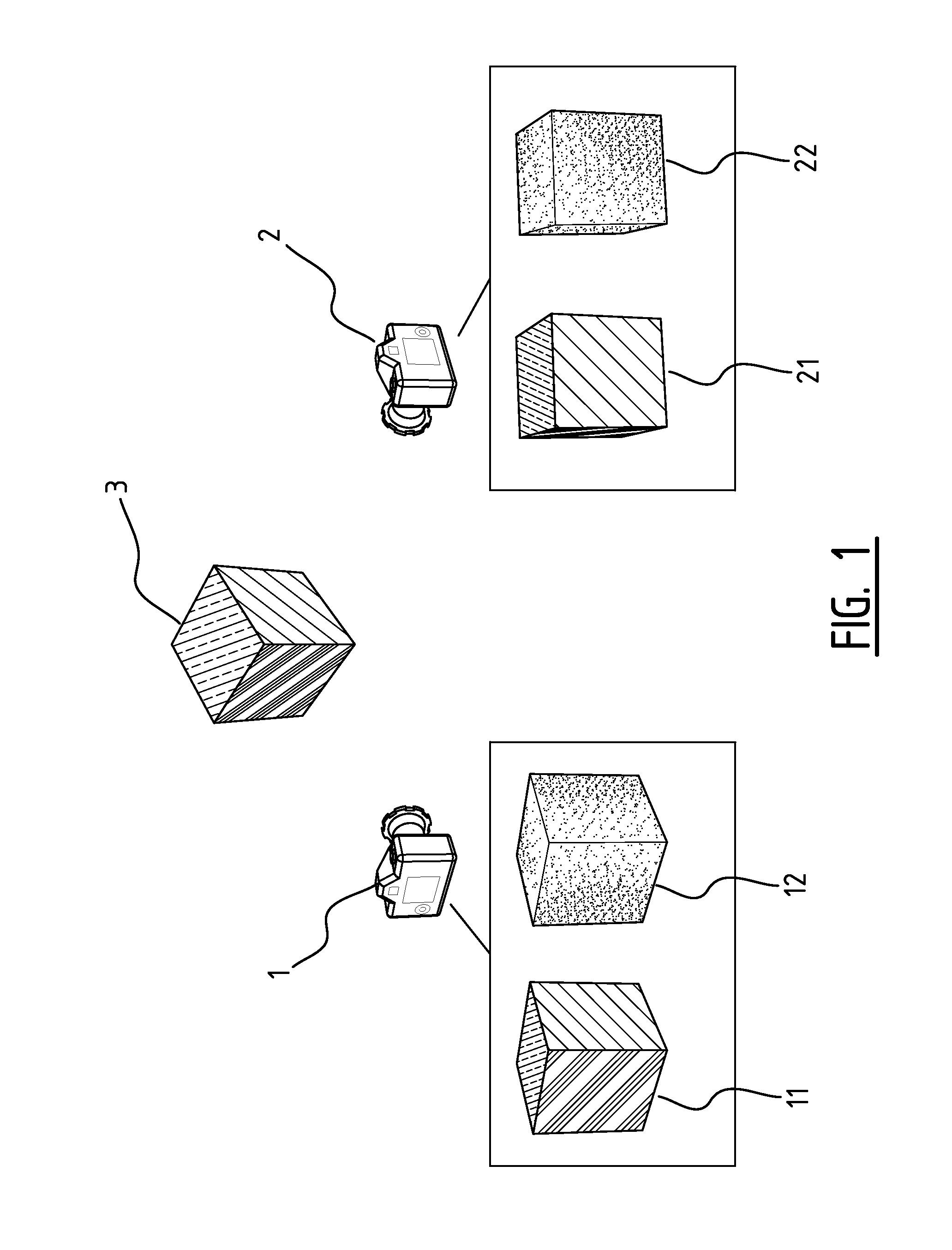
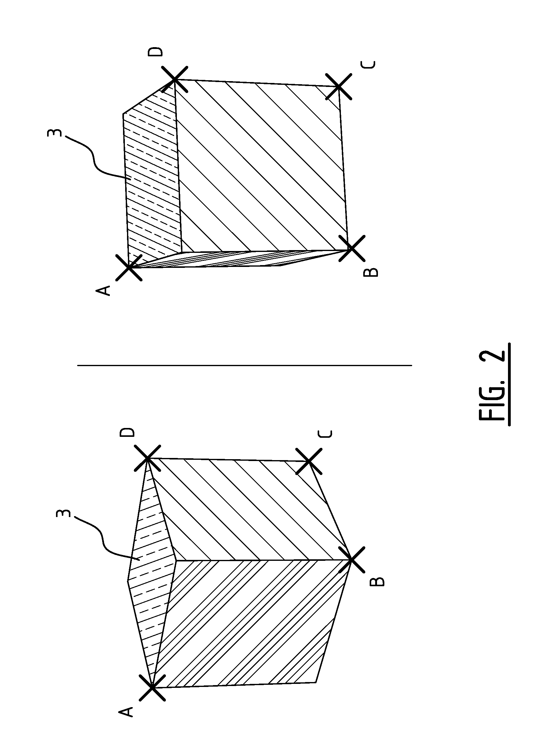
[0058]The above and other advantageous features and objects of the invention will become more apparent and the invention will be better understood from the following detailed description when read in conjunction with the respective figures.

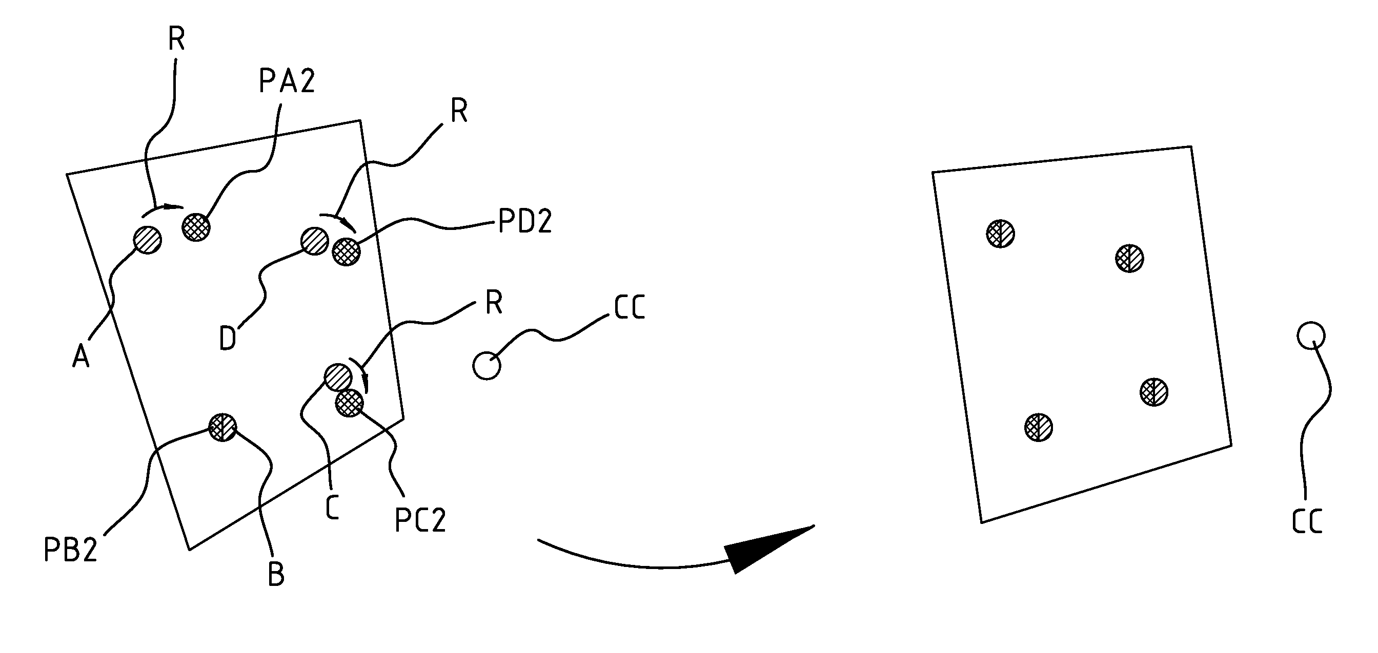
[0059]The description of aspects of the present invention is performed by means of particular embodiments and with reference to certain figures but the invention is not limited thereto. Depicted figures are only schematic and should not be considered as limiting. E.g. certain elements or features may be shown out of proportion or out of scale with respect to other elements.

[0060]In the description of certain embodiments according to the present invention, various features are sometimes grouped together in a single embodiment, figure, or description thereof for the purpose of aiding in the understanding of one or more of the various inventive aspects. This is not to be interpreted as if all features of the group are necessarily present to solve a p...


PUM


Abstract

A method for determining the relative position and orientation of a first and a second imaging device by comparing the image of a commonly depicted object in a first and a second image of the first and the second imaging device respectively, wherein the first and the second imaging devices are adapted for providing first and second depth information respectively for the respective images and in which at least the first and the second depth information is used for the determination. Corresponding device are also disclosed.

Description

TECHNICAL FIELD OF THE INVENTION[0001]The present invention relates to the field of camera calibration techniques and devices therefore. It relates to methods and devices for determining the relative position and orientation of a first and a second imaging device and applications thereof.BACKGROUND OF THE INVENTION[0002]When capturing a scene with two or multiple cameras, the characteristics of these cameras are often needed in order to efficiently use captured data or information, for instance for deriving 3-D information of objects in the scene. These characteristics typically include the location of the cameras, the orientation of the cameras and the internal camera parameters (also called intrinsic parameters) as for instance resolution, field of view, skew, etc. When creating a three-dimensional model of the scene for instance, this information is typically of critical importance. Recovery of the camera information is often called “camera calibration” in the state of the art.[0...

Claims


Application Information

Patent Timeline
Patent Type & Authority Patents(United States)
IPC IPC(8): G06K9/32G01B11/03G01B11/22G01C11/06G06T7/00
CPCG01C11/06G01B11/03G01B11/22G06T7/004G06T2207/10028G06T7/70G06T7/00G06T17/00
Inventor TYTGAT, DONNY
Owner ALCATEL LUCENT SAS
Learn More