
System and a method relating to measuring humidity in a ventilated space

a technology for ventilated spaces and humidity sensors, which is applied in the direction of lighting and heating apparatus, heating types, instruments, etc., can solve the problems of aggravated problems, health problems, and often produced humidity problems, and achieve the effect of reducing or compensating the errors of humidity sensors and good accuracy of measurements

Inactive Publication Date: 2015-03-17
BERGSTEN RIKARD
View PDF10 Cites 9 Cited by
  • Summary
  • Abstract
  • Description
  • Claims
  • Application Information

AI Technical Summary

Benefits of technology

This approach enhances measurement accuracy, reduces errors, and provides flexible, cost-effective, and reliable humidity control, effectively managing ventilation and preventing mold growth in ventilated spaces.

Problems solved by technology

Humidity problems are often produced in cold spaces ventilated by exterior air, often only due to the humidity of the surrounding air and the fact that non-heated spaces often are as cold as, or even colder than, their surroundings and they will therefore accumulate humidity to levels wherein mould, fungi and other microorganisms can grow.
The problems are aggravated if, in addition thereto, there are internal humidity sources such as for example leakage of humid air into an attic space from the living area.
These humidity problems both lead to health problems and to large economical damages.
A property of humidity sensors is that they have a long term stable precision but that they tend to drift in accuracy over time.
The effect thereof is that previous systems either have required a regular calibration or their functioning has been poorer than what would have been possible with accurately calibrated sensors.
So far it has not been possible to provide a system for measuring humidity in a ventilated space with a satisfactory accuracy.
It has also been impossible to provide a system which enables provisioning of reliable measurement data on relative humidity over time and, in general, a system which is flexible.

Method used


Image

  • System and a method relating to measuring humidity in a ventilated space
  • System and a method relating to measuring humidity in a ventilated space
  • System and a method relating to measuring humidity in a ventilated space

Examples


Embodiment Construction

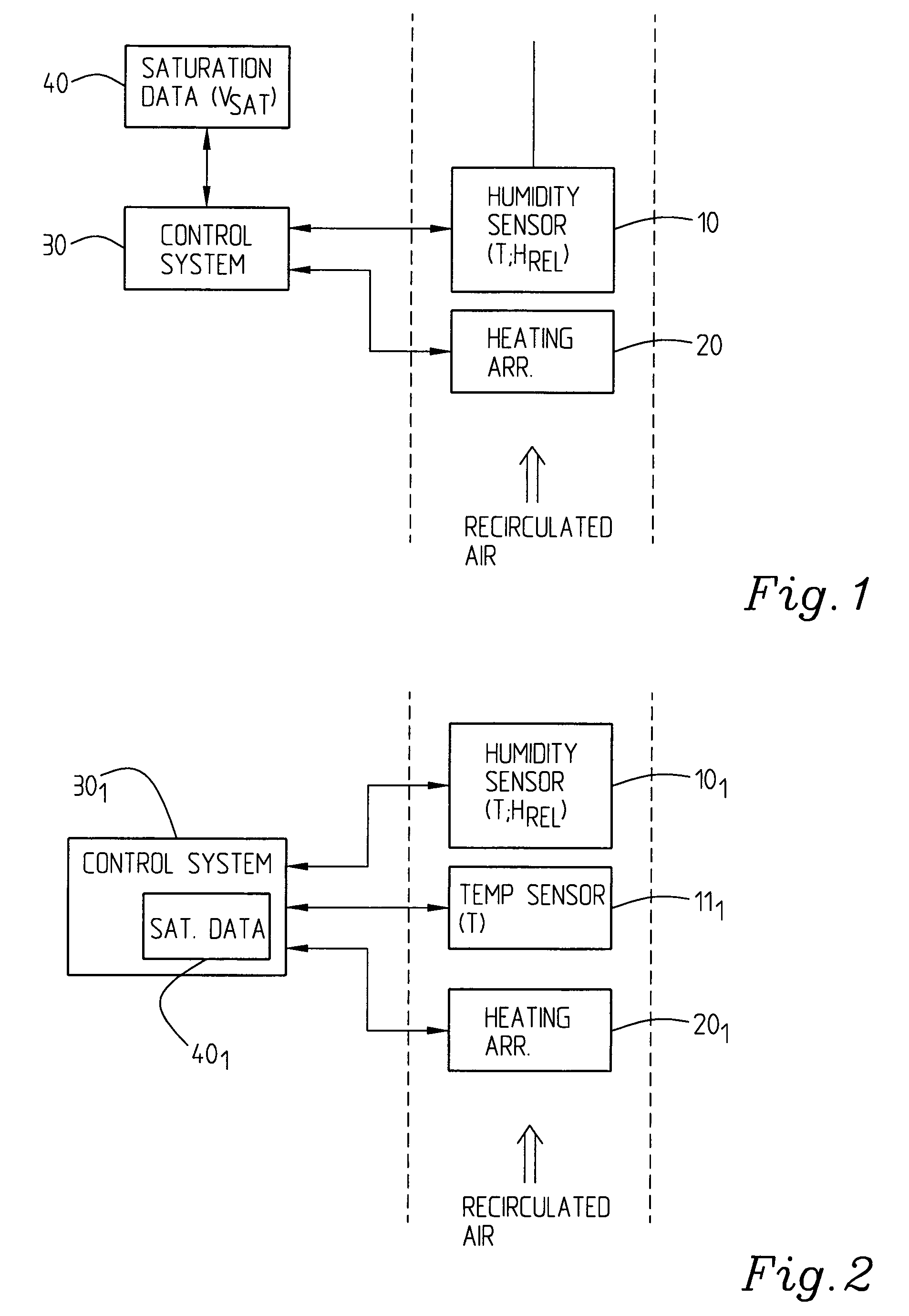
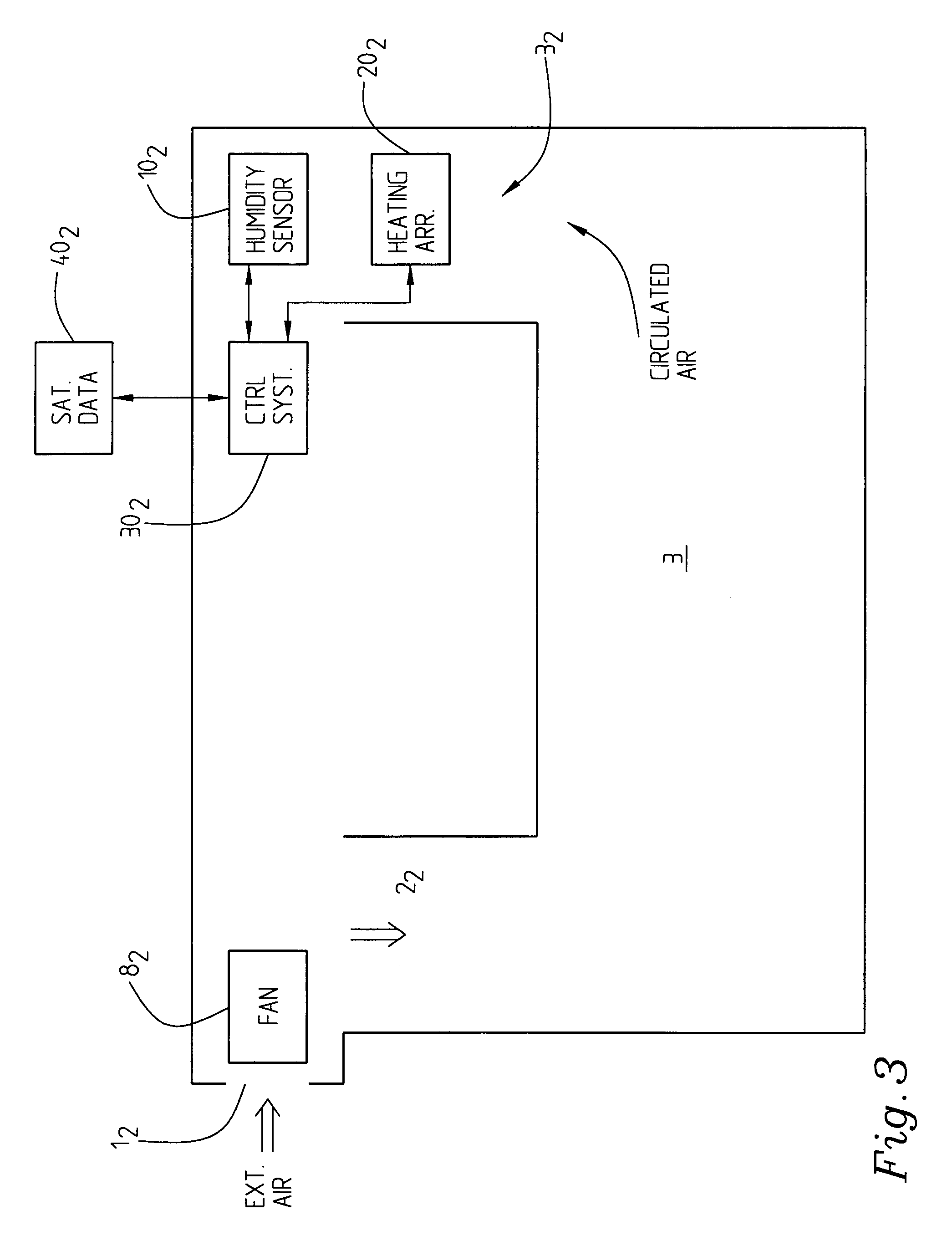
[0036]FIG. 1 illustrates a first embodiment of a system according to the invention which comprises a humidity sensing device 10, here comprising a sensor for measuring both temperature and relative humidity Hrel. It further comprises a heating arrangement 20, for example a heating element. Both the humidity sensor 10 and the heating arrangement 20 are connected to a control system 30 which has access to information for example held in a storing means or a database or similar 40 of saturation data, Vsat, for a number of temperatures. The heating arrangement can be controlled by the control system, switched on, switched off, increased and decreased as to its heating power. The control system also controls the humidity sensor through activating when it is to measure the temperature and the relative humidity, deactivating it when not, possibly also for monitoring purposes.

[0037]Alternatively there is a certain intelligence and controlling processing capacity also in the sensing device i...


PUM

PropertyMeasurementUnit
temperatureaaaaaaaaaa
relative humidityaaaaaaaaaa
temperatureaaaaaaaaaa

Abstract

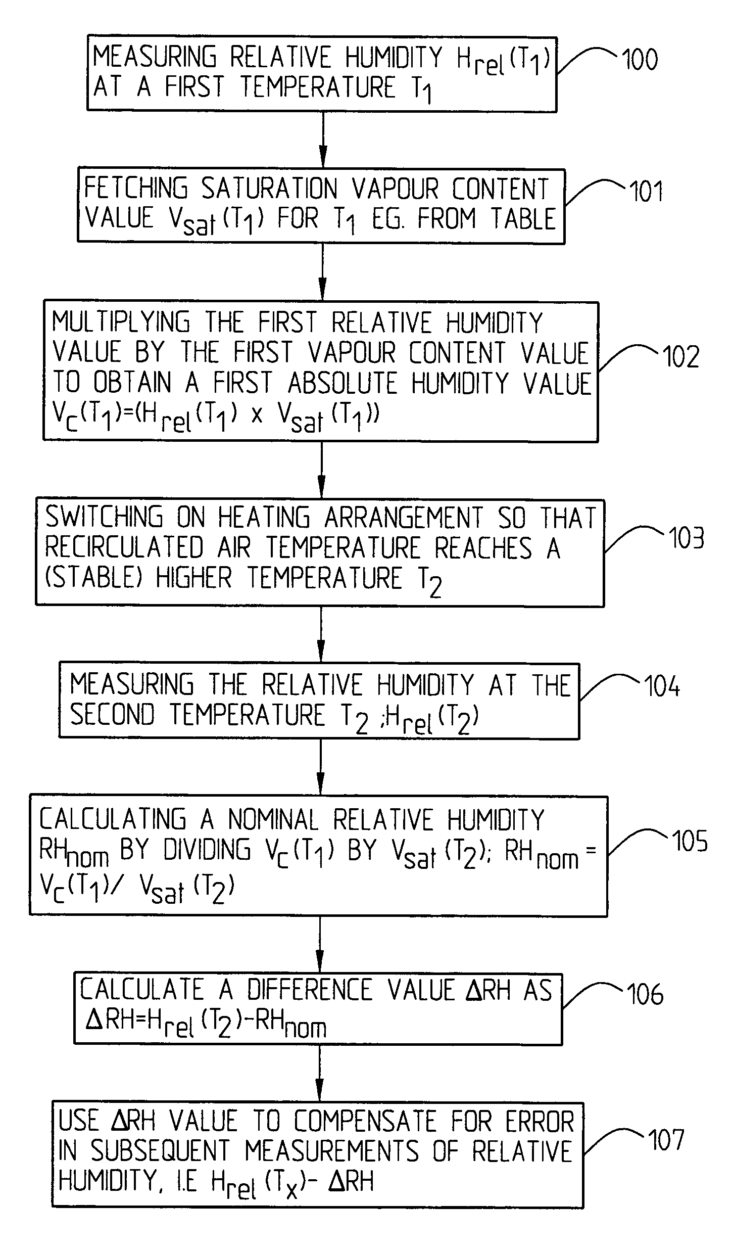
The present invention relates to a system and a method for measuring humidity in a ventilated space (3) comprising humidity sensing means (10), a heating device (201), and a control system (301) having access to pre-stored values on saturation vapor content of air at different temperatures. The relative humidity, Hrel(T1), at a first temperature, T1, is measured, with the heating device inactivate. For TI a pre-stored saturation vapor content value, Vsat(T1), is found. A first absolute humidity value, Vc(T1), is calculated by multiplying the first saturation vapor content value by the first relative humidity value. A second relative humidity, Hrel(T2), at T2 is measured, with the heating device on, a second vapor content value, Hsat(T2), at T2 is found and a nominal relative humidity value, RHnom, is calculated by dividing the first absolute humidity value, Vc(T1), by the second saturation vapor content value, Vsat(T2). The difference, ΔRH, between the second measured relative humidity value, Hrel(T2), and the nominal relative humidity value, RHnom is established and used to adjust subsequent relative humidity measurements for error compensation.

Description

TECHNICAL FIELD[0001]The present invention relates to a system for measuring humidity in a ventilated space, which system comprises a humidity sensing means, and to a corresponding method for measuring humidity in a ventilated space by means of which measurement errors of the humidity sensing means to a high extent or completely can be compensated for.BACKGROUND[0002]Humidity problems are often produced in cold spaces ventilated by exterior air, often only due to the humidity of the surrounding air and the fact that non-heated spaces often are as cold as, or even colder than, their surroundings and they will therefore accumulate humidity to levels wherein mould, fungi and other microorganisms can grow. The problems are aggravated if, in addition thereto, there are internal humidity sources such as for example leakage of humid air into an attic space from the living area. These humidity problems both lead to health problems and to large economical damages.[0003]In order to facilitate...

Claims


Application Information

Patent Timeline
Patent Type & Authority Patents(United States)
IPC IPC(8): G01N7/00G01N37/00F24F5/00F24F11/00G05D22/02
CPCG05D22/02F24F5/0046F24F11/0001F24F11/006F24F11/0012Y02B10/24F24F2005/0064F24F2011/0013F24F2011/0038Y02B10/20F24F2005/0032F24F11/30F24F2110/10F24F2110/12F24F2110/30F24F11/62Y02A30/272F24F11/77F24F11/64E04B1/7069G01D18/006G01N33/0006
Inventor BERGSTEN, RIKARD
Owner BERGSTEN RIKARD
Learn More