Steering support member

a support member and steering shaft technology, applied in the direction of roofs, transportation and packaging, vehicle arrangements, etc., can solve the problems of reducing the rigidity of the open reducing the strength and rigidity of the open side of the steering support member, and reducing the rigidity of the open side. , to achieve the effect of enhancing the support strength and support rigidity of the steering shaft, suppressing steering vibrations, and preventing the lowering of the rigidity of the open

Active Publication Date: 2015-03-17
SUZUKI MOTOR CORP
View PDF17 Cites 5 Cited by
  • Summary
  • Abstract
  • Description
  • Claims
  • Application Information

AI Technical Summary

Benefits of technology

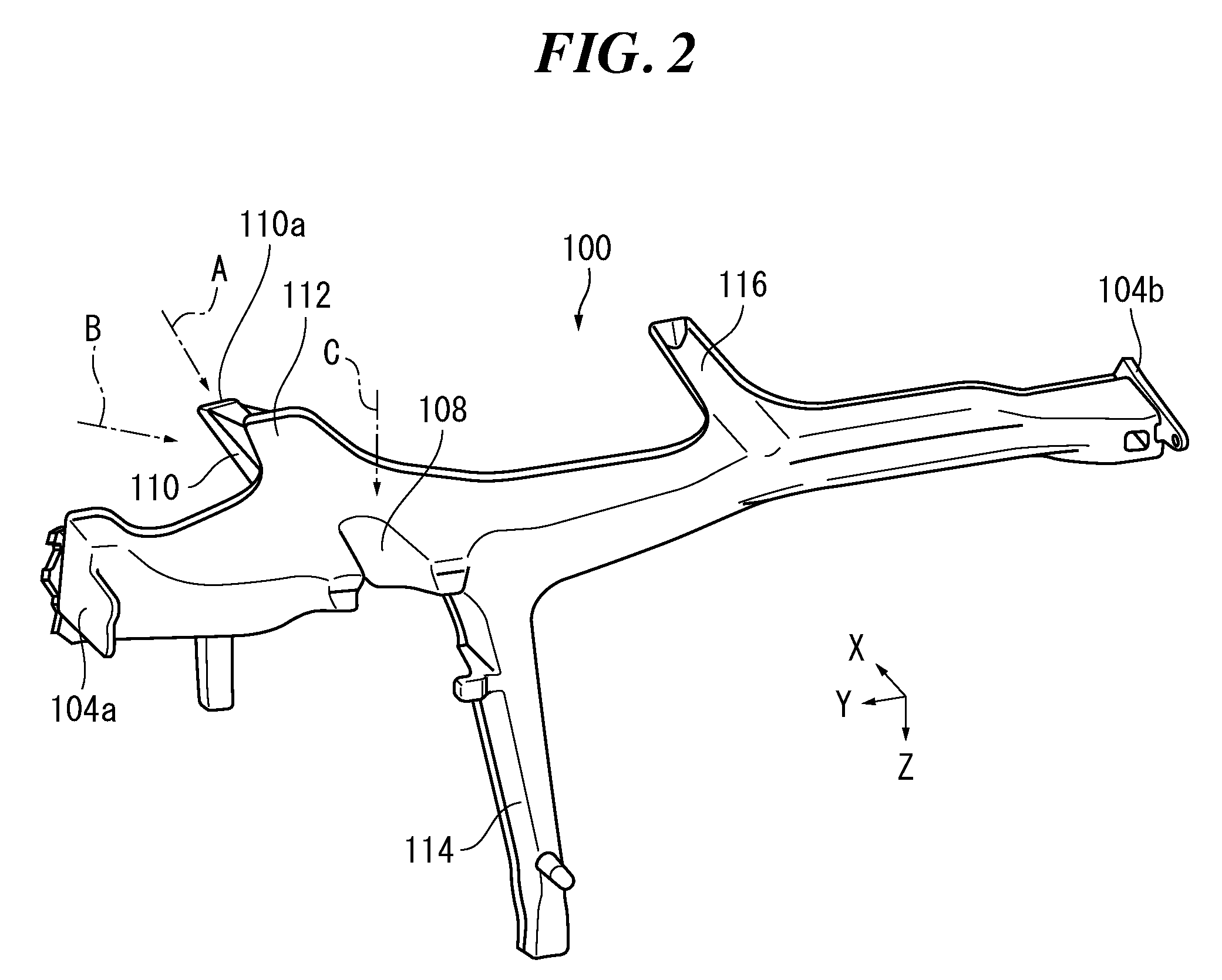
[0014]Because reinforcing ribs molded in one piece with the fixing portion are arranged upright along tangents to circles constituted by a top, a bottom, or any section of the fixing portion, the input load can be smoothly transmitted from the fixing portion to the reinforcing ribs. With the fixing portion and the reinforcing ribs molded in one piece as described above, it is possible to prevent a local concentration of the input load and consequently to enhance support strength and support rigidity of the steering support member. In addition, it is possible to suppress steering vibrations because the support rigidity of the steering support member is enhanced.
[0015]Moreover, because the steering support member is molded in one piece of a light alloy or a resin composite material, the weight and the number of components thereof can be reduced compared to existing steering support members made of iron. In addition, because light alloys or resin composite material have excellent moldability, it is possible to raise a degree of freedom with regard to the shape of the steering support member.
[0017]In this way, because the pair of the first reinforcing ribs and the pair of the second reinforcing ribs inclined in different directions are symmetrically arranged relative to a center line of the fixing portion, the propagation behavior of the input load can be easily analyzed. The analysis results of the propagation behavior of the load can be used to identify, for example, positions to be reinforced. The input load is efficiently dispersed by the reinforcing ribs arranged as described above, and it is possible to enhance the strength and rigidity of the steering support member.
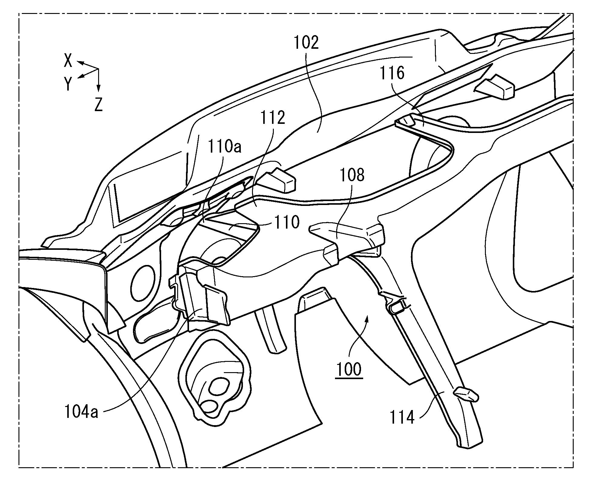
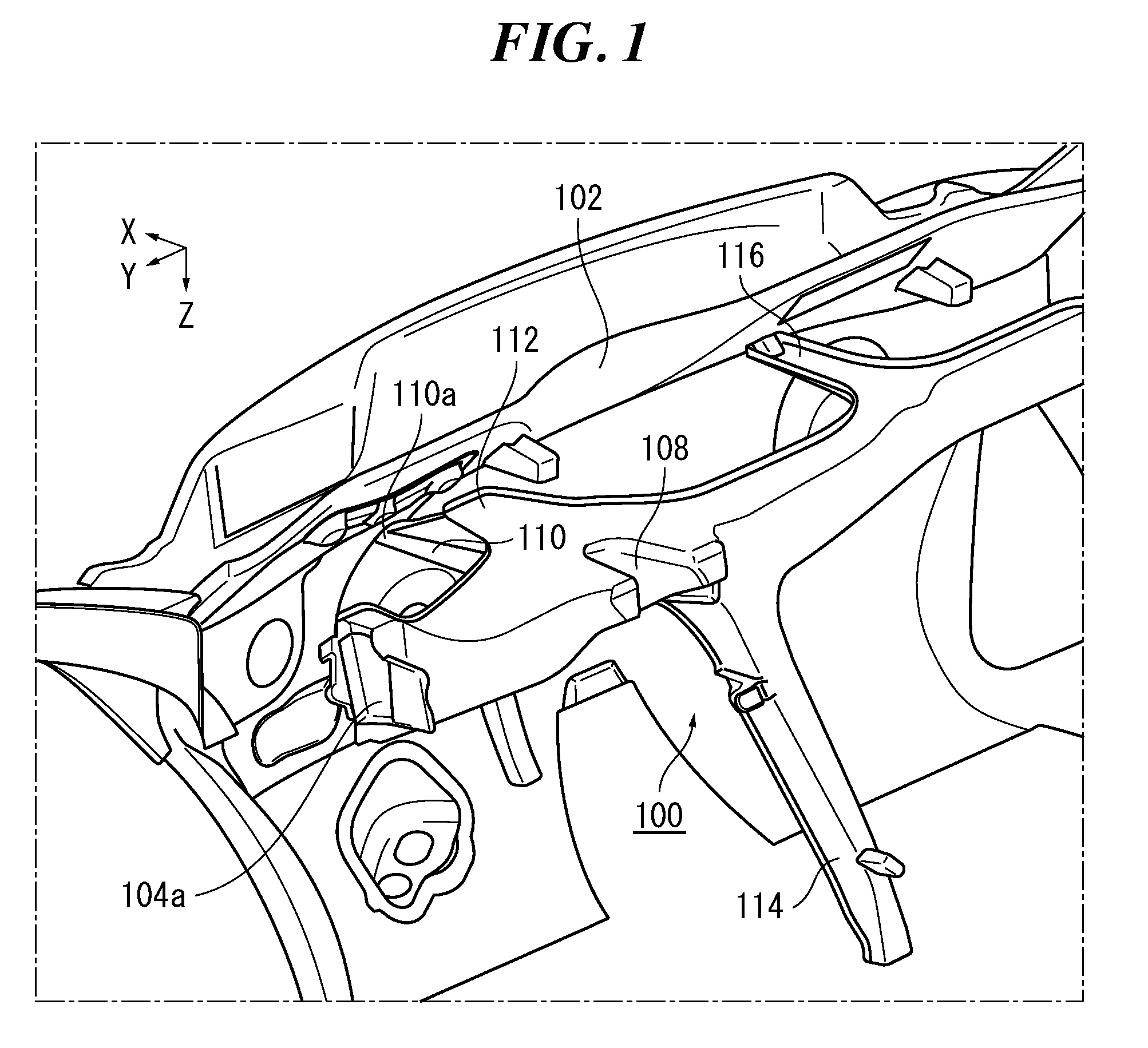
[0019]Thus, a triangular area projecting toward the vehicle front side is formed in the steering support member. Forming the triangular area with the second reinforcing ribs and the projecting portion of the upper flange means that the second reinforcing ribs widen toward the upper side. Therefore, the open side of the U-shaped longitudinal section is supported by the triangular area in the steering support member. Although the rigidity of the open side of the U-shaped longitudinal section is low, it is possible to prevent the lowering of the rigidity of the open side because it is supported by the triangular area. The projecting portion is supported by the second reinforcing ribs constituting the triangular area. Therefore, the steering support member having the U-shaped longitudinal section is reinforced by the triangular area and is not deformed even if a load is input to the fixing portion.
[0020]The steering support member may further comprise: a mounting portion that is arranged inside or in the vicinity of the triangular area and on which the steering shaft can be mounted. Thus, the steering shaft is mounted on the firm mounting portion arranged inside or in the vicinity of the triangular area constituting a reinforcing structure. Consequently, it is possible to enhance support strength and support rigidity of the steering shaft, and to suppress steering vibrations.
[0023]In accordance with the present invention, it is possible to provide a steering support member that can achieve enhanced support strength and support rigidity while reducing its weight.

Problems solved by technology

If the rigidity of the steering support member is low, vibrations from the vehicle body (e.g., the suspension) or engine vibrations when idling are transmitted to the steering mechanism, and the so-called steering vibrations that make occupants feel uncomfortable may occur.
Sufficient strength and rigidity on the open side of the steering support member may not be obtained if a longitudinal section thereof has a U shape.
However, this will make the steering support member heavy and make it difficult to reduce its weight.

Method used


Image

  • Steering support member
  • Steering support member
  • Steering support member

Examples


Embodiment Construction

[0032]The detailed description set forth below in connection with the appended drawings is intended as a description of various aspects of the present disclosure and is not intended to represent the only aspects in which the present disclosure may be practiced. Each aspect described in this disclosure is provided merely as an example or illustration of the present disclosure, and should not necessarily be construed as preferred or advantageous over other aspects. The detailed description includes specific details for the purpose of providing a thorough understanding of the present disclosure. However, it will be apparent to those skilled in the art that the present disclosure may be practiced without these specific details. In some instances, well-known structures and devices are shown in block diagram form in order to avoid obscuring the concepts of the present disclosure. Acronyms and other descriptive terminology may be used merely for convenience and clarity and are not intended...


PUM


Abstract

A steering support member according to the present invention supports a steering shaft, extends in a vehicle width direction and is fixed at both ends to lateral sides of a vehicle, is molded of a light alloy or a resin composite material. And the steering support member includes a fixing portion having a shape of a truncated cone that extends toward a vehicle front side from the vicinity of a position supporting the steering shaft, a top of the fixing portion being fixed to a dash panel delimiting an engine room in a vehicle front portion, and a plurality of reinforcing ribs that are arranged upright along tangents to a circle constituted by the top of the fixing portion and to a bottom circle.

Description

CROSS-REFERENCE TO RELATED APPLICATION[0001]This application claims the benefit of and priority to Japanese Application No. 2012-207789 filed on Sep. 21, 2012 and entitled “Steering support member”, which is assigned to the assignee hereof and which is incorporated herein by reference.FIELD[0002]This disclosure relates to a steering support member supporting a steering shaft and the like and extending in a vehicle width direction.BACKGROUND[0003]In a vehicle such as an automobile, a steering support member is arranged, for example, in a space partitioned with a dash panel and an instrument panel. The dash panel is a vehicle body panel that is located in a vehicle front portion and delimits an engine room from a vehicle compartment. The instrument panel is an interior component arranged on a compartment side of the dash panel.[0004]The steering support member is a member that extends in a vehicle width direction and both ends of which are fixed to the lateral sides of the vehicle suc...

Claims


Application Information

Patent Timeline
Patent Type & Authority Patents(United States)
IPC IPC(8): B62D25/14
CPCB62D25/145
Inventor ATSUMI, RYO
Owner SUZUKI MOTOR CORP
Why Eureka
Try Eureka