Capacitor module

a technology of capacitors and modules, applied in the direction of multiple hybrid/edl capacitors, coupling device connections, transportation and packaging, etc., to achieve the effects of reducing vibration, preventing breakage, and enhancing vibration resistan

Active Publication Date: 2015-03-17
PANASONIC CORP
View PDF8 Cites 1 Cited by
  • Summary
  • Abstract
  • Description
  • Claims
  • Application Information

AI Technical Summary

Benefits of technology

[0011]The present invention has been accomplished to solve the problems to be solved experienced by the prior art. Therefore, an object of the present invention is to provide a capacitor module having an excellent assembling workability and an improved vibration resistance.
[0013]As described above, according to the present invention, the first and second holding portions urge the leg of the lead wire toward the capacitor body so as to apply a pressing force to a part of the leg in the axial direction. Therefore, it is possible to produce the effects of the suppression of vibrations at the leg of the led wire, the prevention of breakage near to the soldered portion of the lead wire, the enhanced vibration resistance, and the secured excellent assembling workability as well as the suppression of damage on the capacitor during assembling work.

Problems solved by technology

These clearances cause vibrations in the barrel of the capacitor due to the vibration of the vehicle, thereby raising problems to be solved such as the rupture of the lead wire in the vicinity of the soldered portion of the lead wire and the breakage of the soldered portion.

Method used


Image

  • Capacitor module
  • Capacitor module
  • Capacitor module

Examples


first exemplary embodiment

[0025]A description will be given below of a capacitor module in a first exemplary embodiment according to the present invention.

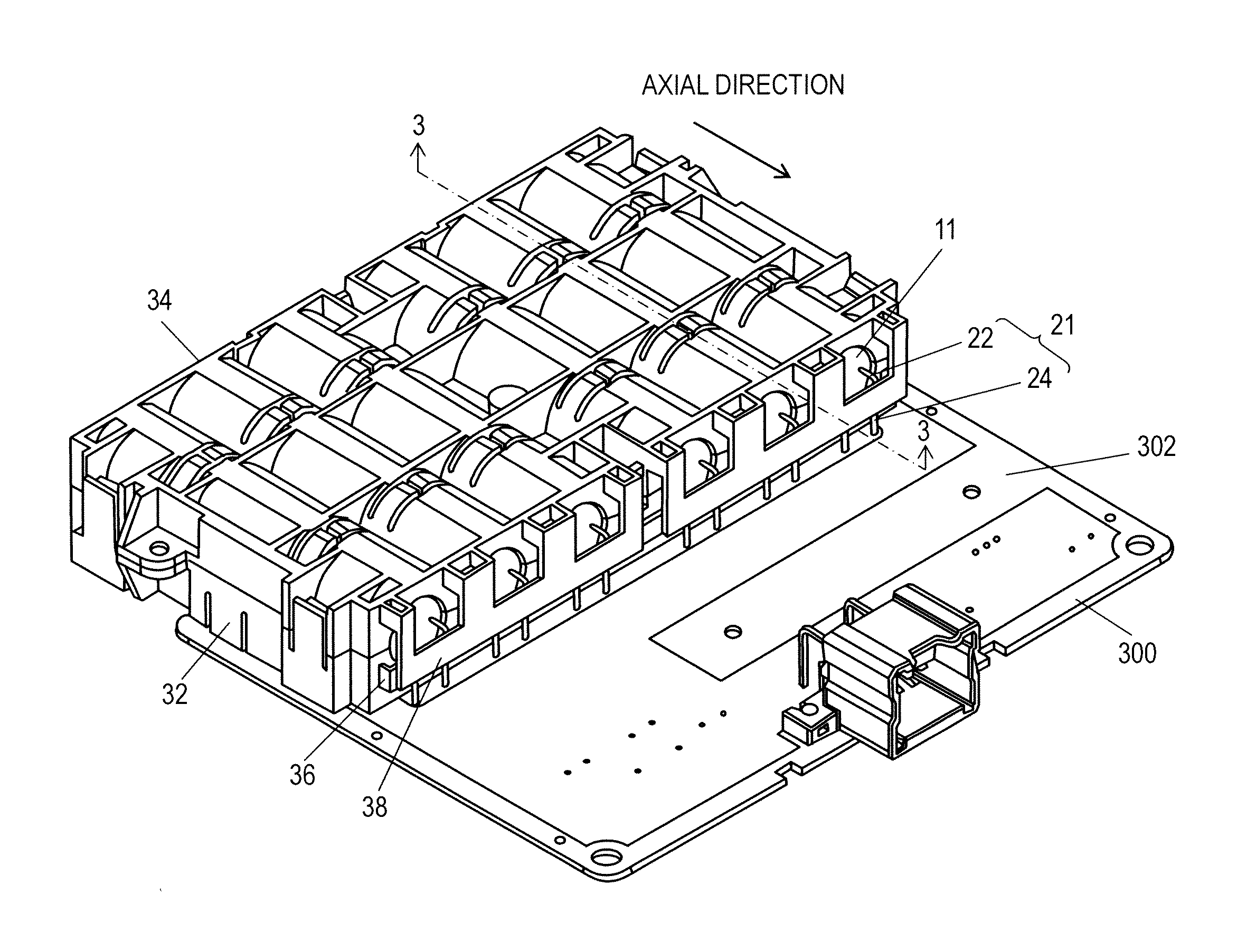
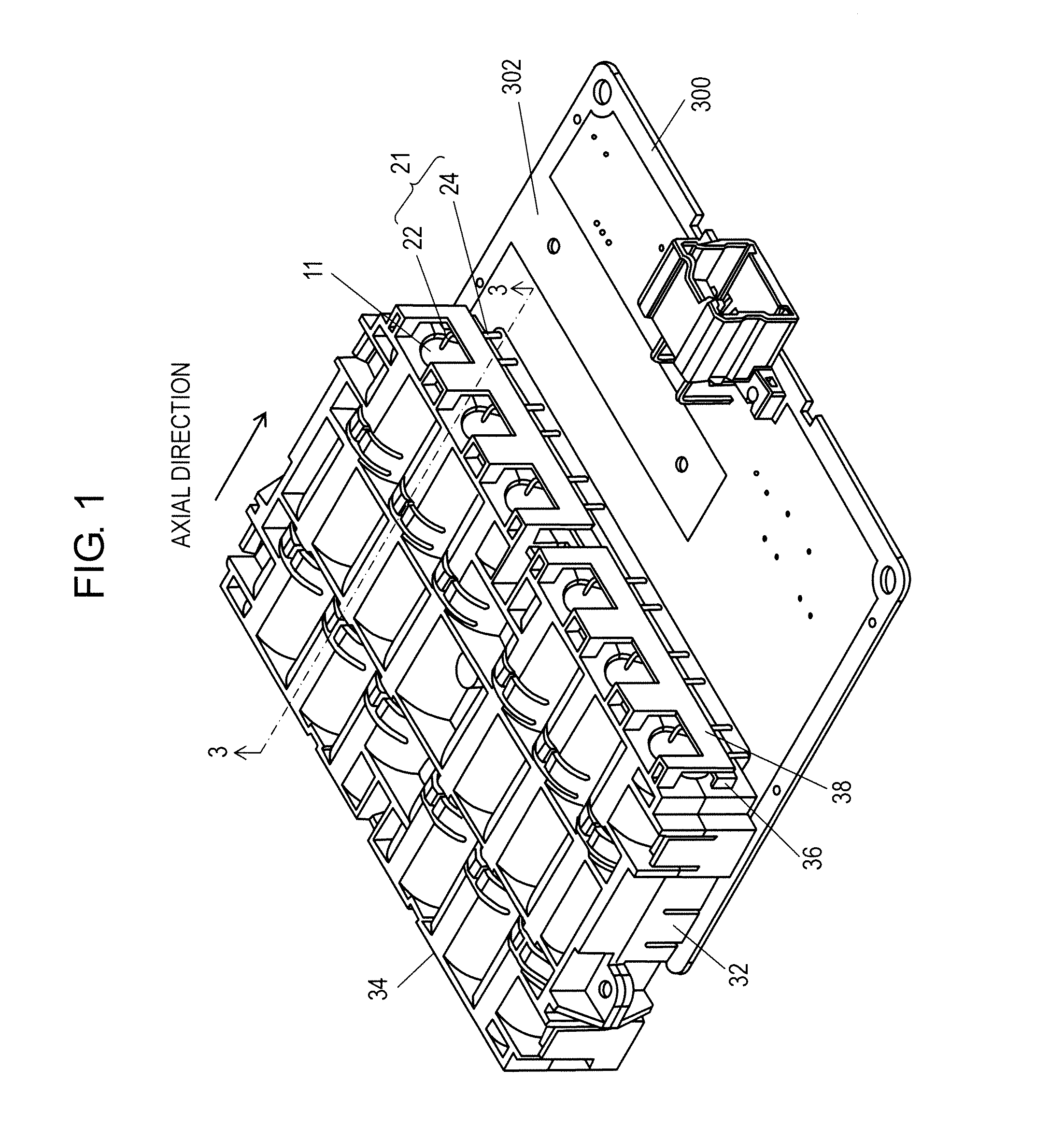
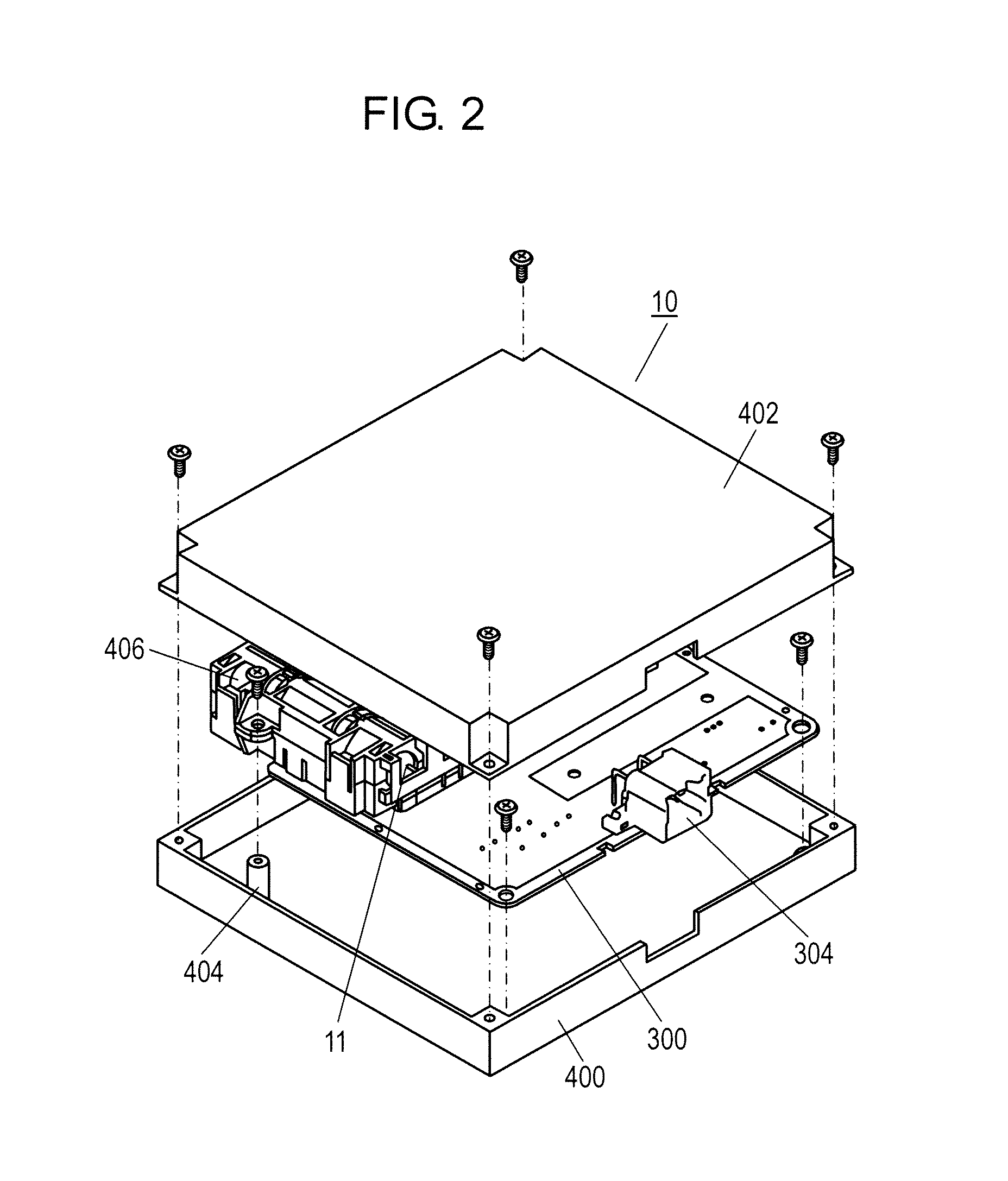
[0026]FIG. 1 is an upward perspective view showing a capacitor module contained in holders in a first exemplary embodiment according to the present invention; and FIG. 2 is an exploded perspective view showing the capacitor module.

[0027]As shown in FIG. 2, capacitor module 10 includes a plurality of capacitors electrically connected to each other inside of exterior cases 400 and 402 made of an insulating resin, and thus, is adapted to accumulate electric power in a plurality of capacitors 11 from an outside power source via connector 304 so as to supply the accumulated electric power to outside loads or the like through connector 304. Wiring board 300 is provided with a control circuit for controlling the electric charging / discharging of the plurality of capacitors 11.

[0028]As shown in FIG. 1, six electric double-layered capacitors are juxtaposed in capaci...

second exemplary embodiment

[0089]A description will be given in a second exemplary embodiment with reference to FIG. 10. FIG. 10 is a cross-sectional view showing a capacitor module in the second exemplary embodiment according to the present invention. Here, the same reference numerals are assigned to the same constituent elements as those in the first exemplary embodiment, and therefore, their description will be omitted below.

[0090]As shown in FIG. 10, leg 24a of lead wire 21a is slantwise led out in such a manner as to be separated from capacitor body 12 downward of board surface 302.

[0091]In the led-out state of lead wire 21a, supporter 102 of first holding portion 36 abuts against lead wire 21a at the edge of the upper end of supporter 102, and thus, supports it. Furthermore, projecting presser 206 of second holding portion 38 abuts against leg 24a of lead wire 21a downward of the abutment portion of first holding portion 36.

[0092]In other words, a distance from board surface 302 to a point of first hold...


PUM


Abstract

A capacitor body is laterally contained in a lower holder, to be then pressed by an upper holder. A lead wire is led from the capacitor body in an axial direction, and then, bent toward a wiring board, thereby forming a leg soldered to the wiring board. The lower holder includes a first holding portion extending outward and having a supporter disposed in a stationary state whereas the upper holder includes a second holding portion extending outward and having a bridge stretched between a pair of elastically deformable arms. The first and second holding portions are urged toward the capacitor body, and therefore, axially hold a part of the leg of the lead wire. This configuration can prevent any breakage of a soldered portion of the lead wire due to vibrations so as to enhance vibration resistance.

Description

BACKGROUND OF THE INVENTION[0001]1. Field of the Invention[0002]The present invention relates to a capacitor module having a capacitor mounted on a wiring board.[0003]2. Description of the Related Art[0004]Vehicles such as an electric-powered car or a hybrid car have been commercially available in recent years for the purpose of environmental friendliness and fuel economy enhancement. Such vehicles intermittently consume a large amount of current when a stator is driven during use, and therefore, a voltage in a battery temporarily decreases. Consequently, voltages to be supplied to other loads such as audio equipment, a car navigator, and an electronic controller in a vehicular control system also decrease, thereby raising a fear of unstable operation.[0005]Taking measures against that, a capacitor module with a capacitor has been known as an auxiliary power source for sufficiently supplying electric power to loads when a voltage in a battery temporarily decreases.[0006]FIG. 11 is a...

Claims


Application Information

Patent Timeline
Patent Type & Authority Patents(United States)
IPC IPC(8): H01G11/10H01G2/04H01G9/008H01G11/76H01G11/82
CPCH01G11/10H01G9/008H01G11/82H01G11/76H01G2/04Y02T10/7022Y02E60/13Y02T10/70
Inventor MORITA, KAZUKININOMIYA, TOORUINOUE, TATEHIKO
Owner PANASONIC CORP
Why Eureka
Try Eureka