
Generator torque control methods

a technology of generator torque and control method, which is applied in the direction of motors, wind energy generation, dynamo-electric machines, etc., can solve the problems of generators that cannot the generator is unable to export power to the supply network, and the drive train of serious mechanical oscillations of wind turbines, etc., to achieve a rapid reduction of the dbr and the associated actuator or switchgear, the effect of significantly reducing the dbr

Active Publication Date: 2015-03-17
GE ENERGY POWER CONVERSION TECH
View PDF5 Cites 4 Cited by
  • Summary
  • Abstract
  • Description
  • Claims
  • Application Information

AI Technical Summary

Benefits of technology

[0033]The pitch of the at least one turbine blade may be altered or adjusted under the control of a pitch actuator. The method may therefore further include the step of altering the pitch of the at least one turbine blade to minimise peak generator speed during a fault condition. In other words, the pitch of the at least one turbine blade may be altered so that the turbine assembly captures less wind and any increase in the speed of rotation of the output shaft (and hence the rotor assembly of the generator) as a result of the fault condition is minimised. The pitch of the at least one turbine blade can be varied as soon as a fault condition is detected or at any other time.
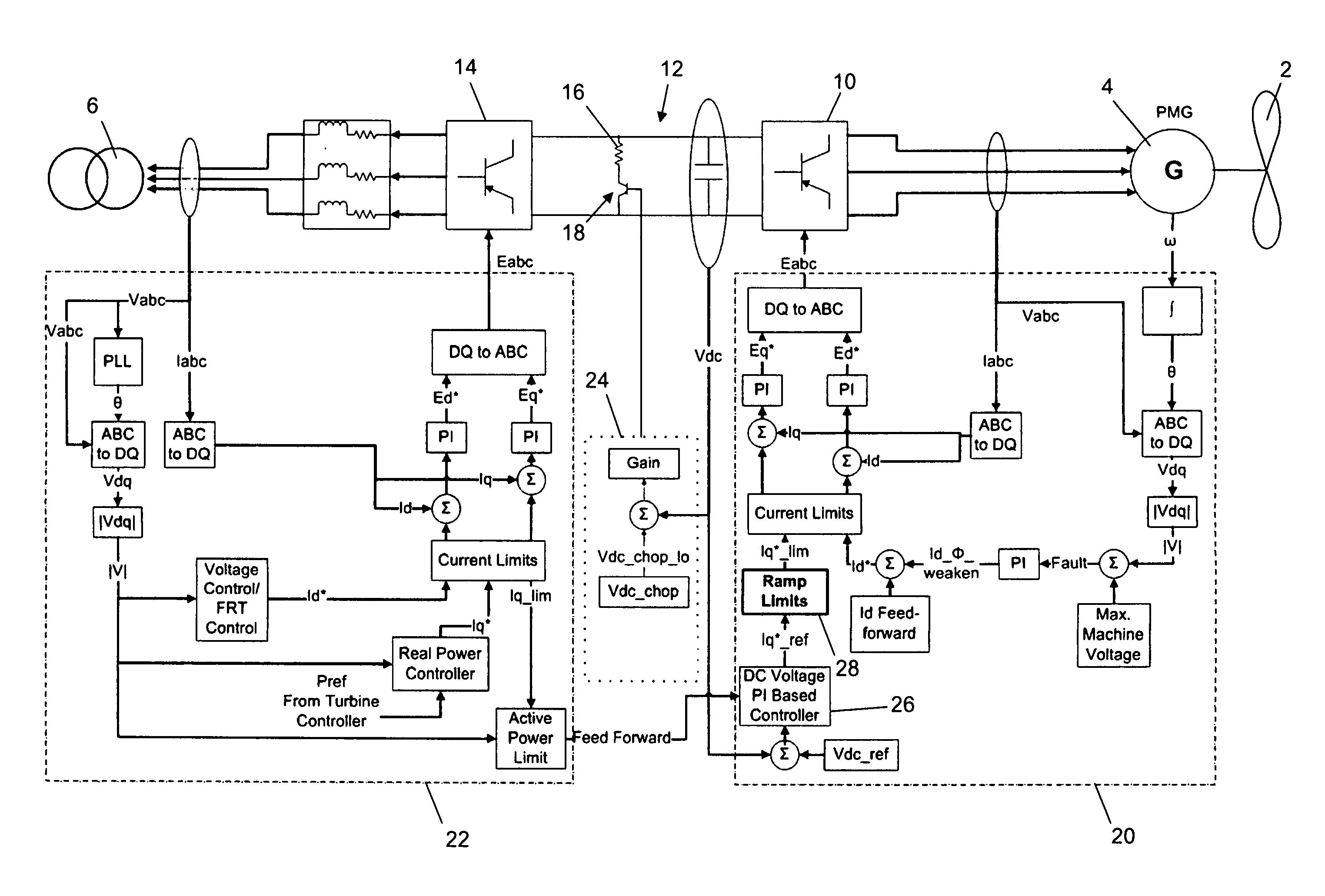
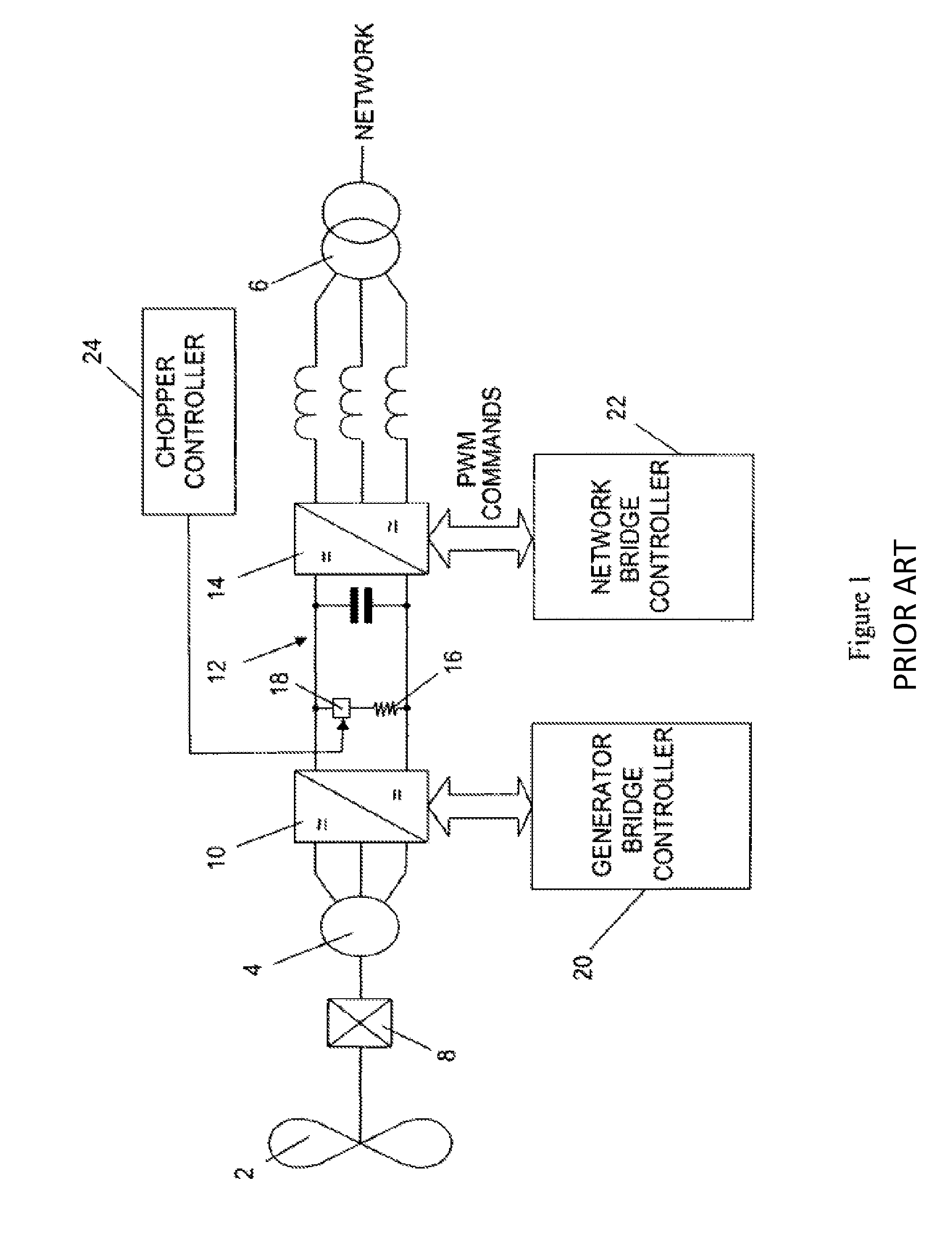
[0035]Typically the generator is connected to a power converter which interfaces the generator to a supply network or power grid. The power converter can have any suitable topology but in one arrangement includes a generator bridge connected to a network bridge by a dc link. A dynamic braking resistor (DBR) can be connected in series with an actuator or switchgear across the dc link. The rating of the DBR and the associated actuator or switchgear can be significantly reduced if the generator torque is made to decrease at a substantially constant rate as described above. This is because power flow into the DBR can be rapidly reduced, thereby ensuring that the total amount of energy that is absorbed by the DBR as a result of the fault condition is minimised. The DBR can have a smaller rating than would be the case for a conventional wind turbine and power converter assembly where the generator power is absorbed for the full duration of the fault condition. This means that the DBR can be made physically smaller and the cooling requirements are significantly reduced leading to cost savings.

Problems solved by technology

Sudden changes in generator torque can cause serious mechanical oscillations in the drive train of the wind turbine.
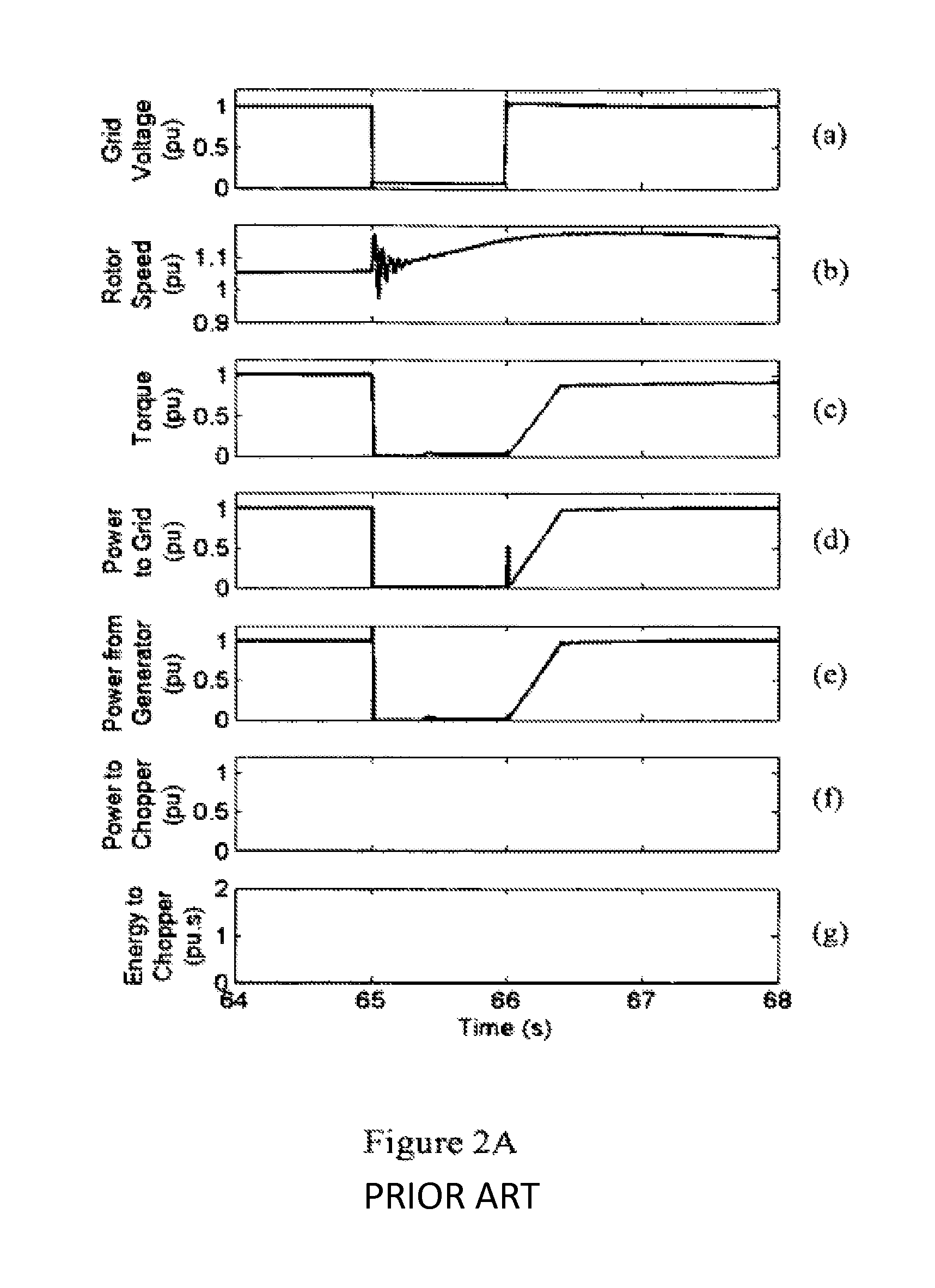
Such changes can occur during a grid fault where the inability to export power into the supply network results in a near simultaneous step reduction in generator torque, or as a result of a fault in the power converter.
During such grid faults or transients the generator is unable to export power to the supply network.
The inability to export power to the supply network during the grid fault also causes the speed of the generator rotor to increase to a peak speed at about time t=66.5 s before starting to gradually decrease.

Method used


Image

  • Generator torque control methods
  • Generator torque control methods
  • Generator torque control methods

Examples


Embodiment Construction

[0045]The generator torque control method of the present invention is best understood with reference to FIGS. 2C and 2D. Each Figure includes a series of seven graphs labelled (a) to (g) as described above and which show how the operational parameters of the wind turbine and power converter assembly of FIG. 1 vary in a pu or “per unit” system during a grid fault where the grid voltage in the supply network dips to zero for one second. FIG. 2C shows how the operational parameters vary in a situation where the generator torque is made to decrease as soon as the grid fault is detected. FIG. 2D shows how the same operational parameters vary in a situation where the generator torque is held substantially constant for 0.5 s before it is made to decrease.

[0046]It can be seen from graphs (a) of FIGS. 2C and 2D that the grid voltage undergoes a step reduction from 1 to 0 at time t=65 s, remains at 0 for one second and recovers with a step increase from 0 to 1 at time t=66 s. For the reasons ...


PUM


Abstract

A wind turbine typically includes a generator and a rotating mechanical system having a natural period. The present invention relates to a method of controlling generator torque that minimizes oscillations in the speed of the generator rotor. In the event of a grid fault or transient, or a fault in the power converter, the generator torque is decreased at a substantially constant rate with respect to time. The rate at which the generator torque is decreases is proportional to the nominal rated torque of the generator and inversely proportional to an integer multiple of the natural period of the rotating mechanical system.

Description

FIELD OF THE INVENTION[0001]The present invention relates to generator torque control methods, and in particular to methods for controlling torque in the generator of a wind turbine during a fault condition.BACKGROUND OF THE INVENTION[0002]It is possible to convert wind energy to electrical energy by using a wind turbine to drive the rotor of a generator, either directly or by means of a gearbox. The ac frequency that is developed at the stator terminals of the generator (the “stator voltage”) is directly proportional to the speed of rotation of the rotor. The voltage at the generator terminals also varies as a function of speed and, depending on the particular type of generator, on the flux level. For optimum energy capture, the speed of rotation of the output shaft of the wind turbine will vary according to the speed of the wind driving the turbine blades. To limit the energy capture at high wind speeds, the speed of rotation of the output shaft is controlled by altering the pitch...

Claims


Application Information

Patent Timeline
Patent Type & Authority Patents(United States)
IPC IPC(8): F03D9/00H02P9/04F03D7/02H02K7/18H02P9/00H02P9/48
CPCH02P9/04F03D7/0224F03D9/003H02P9/48H02P9/006Y02E10/725H02K7/1838Y02E10/723F03D9/255Y02E10/72F03D7/04H02K7/18
Inventor BANHAM-HALL, DOMINIC DAVIDTAYLOR, GARETH ANTHONYSMITH, CHRISTOPHER ALAN
Owner GE ENERGY POWER CONVERSION TECH
Learn More