Pushbits for semi-synchronized pointing

a technology of pushbits and pointing points, applied in the direction of electric controllers, program control, instruments, etc., can solve the problem of the number of light sources, and achieve the effect of simplifying the coding

Inactive Publication Date: 2015-03-17
SIGNIFY HLDG BV +1
View PDF14 Cites 2 Cited by
  • Summary
  • Abstract
  • Description
  • Claims
  • Application Information

AI Technical Summary

Benefits of technology

[0008]It is an object of the present invention to overcome at least some of these problems, and to provide a lighting system control that simplifies the coding.

Problems solved by technology

There are problems with such a lighting system.
One problem is related to synchronization.
Another problem is related to the number of light sources.
In order to be useful in practice the light sources will have to be equipped with multiple code schemes for the beacons, which is cumbersome.

Method used


Image

  • Pushbits for semi-synchronized pointing
  • Pushbits for semi-synchronized pointing
  • Pushbits for semi-synchronized pointing

Examples


Embodiment Construction

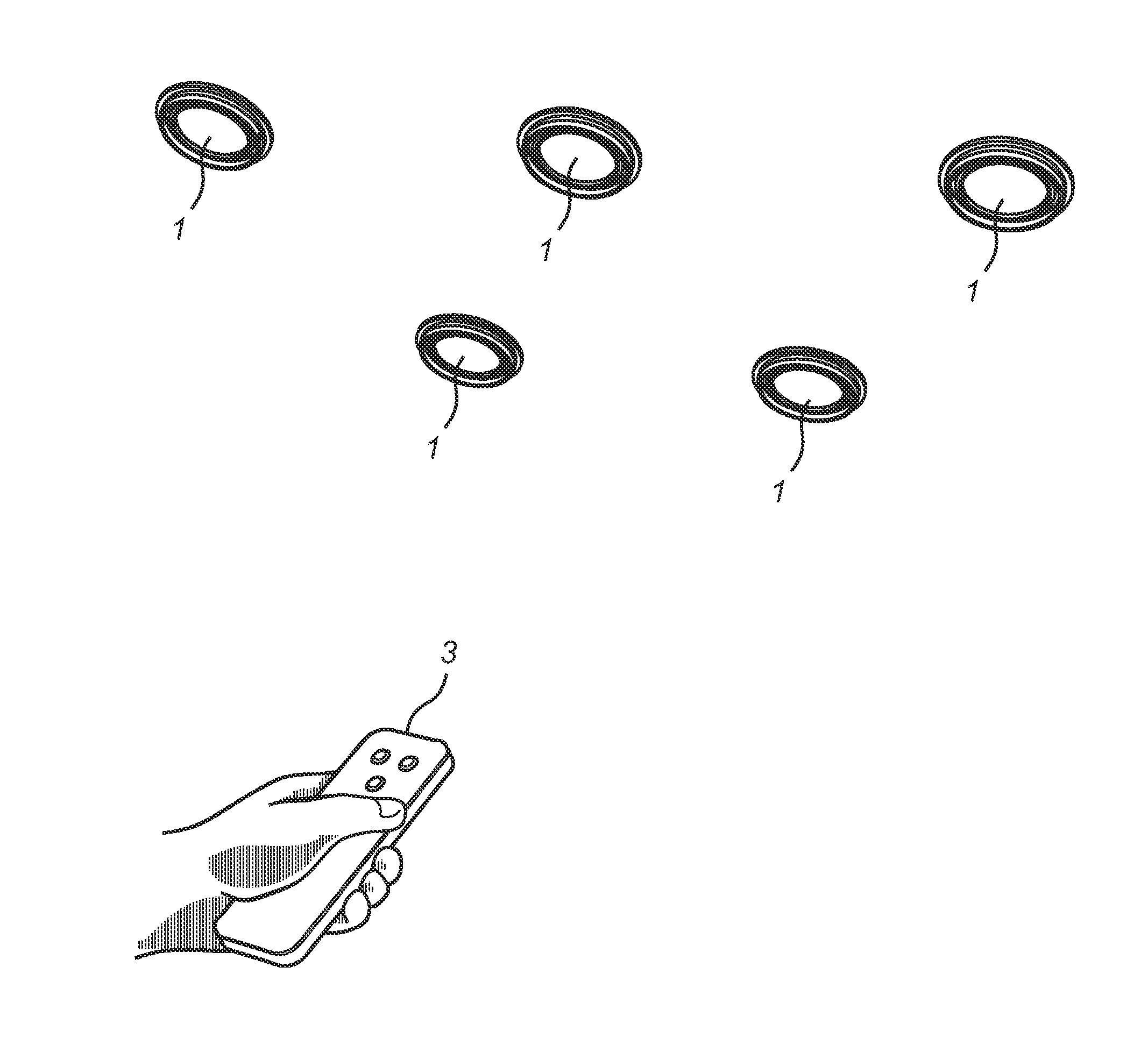
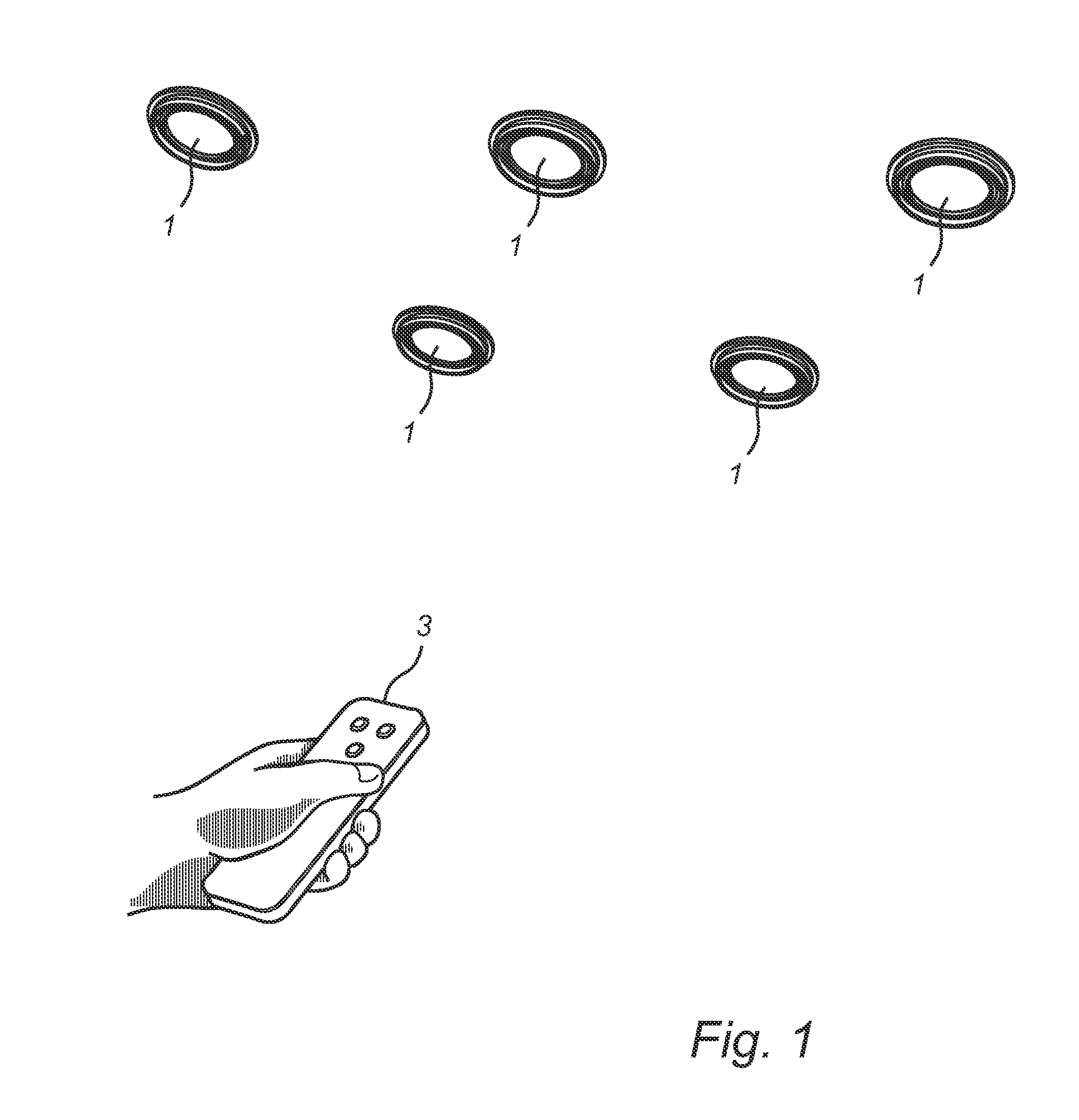
[0026]Referring to FIG. 1, an embodiment of a lighting system according to this invention comprises several light sources (LS) 1, and a remote controller (RC) 3, which is used to control the settings of the light sources.

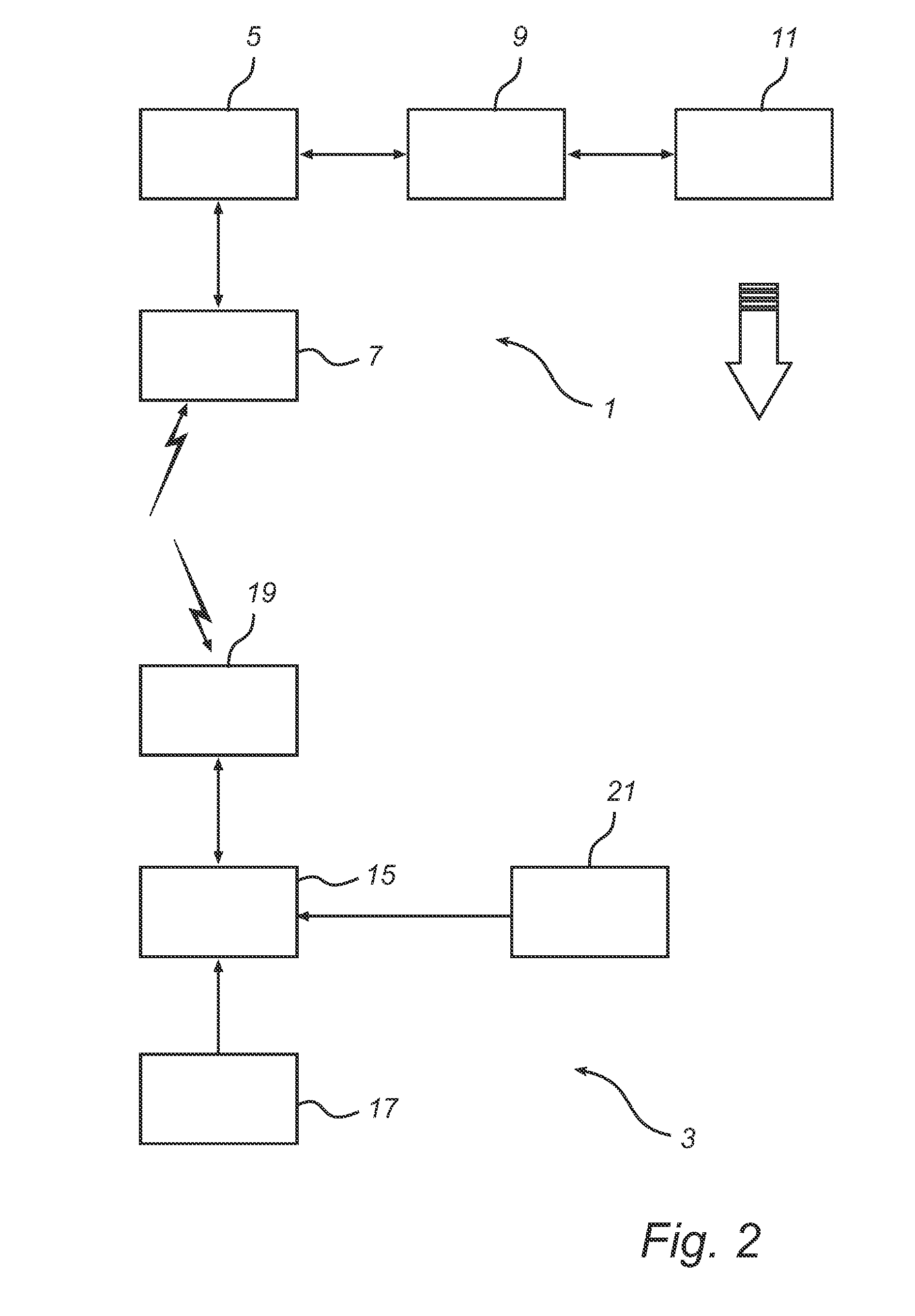
[0027]In order to explain the communication between the remote controller 3 and the light sources 1FIG. 2 shows a block diagram of an embodiment of the remote controller (RC) 3 as well as a light source (LS) 1. The light source 1 comprises a control unit 5, an RF (radio frequency) module 7, connected with the control unit 5, a light element driver 9, connected with the control unit 5, and a set of light elements 11, including at least one light element, connected with the light element driver 9.

[0028]The remote controller 3 comprises a control unit 15, a control mechanism 17, connected with the control unit 15, an omnidirectional transmitter, which in this embodiment is an RF (Radio Frequency) transmitter comprised in an RF module 19 in conjunction with a radio rece...


PUM


Abstract

A method of selecting a light source among a plurality of light sources by means of a remote controller includes the remote controller: instructing, by omnidirectional transmission, the light sources to each transmit a directional signal comprising a code, which is unique for each light source; —receiving the directional signals from the light sources; and selecting one of the light sources on basis of the received directional signals. Furthermore, the method includes: generating, remotely of the light sources, codes to be transmitted by the light sources; and—the remote controller instructing each one of the light sources which one of the remotely determined codes to transmit.

Description

FIELD OF THE INVENTION[0001]The present invention is related to remote control of a lighting system, and more particularly to the selection of a particular light source among a plurality of light sources by means of a remote controller.BACKGROUND OF THE INVENTION[0002]In a lighting system having several individual light sources which are capable of communicating with a remote controller, a desired control feature is to be able to control the light output of an individual light source merely by pointing at it with the remote controller and operating a control mechanism, such as buttons or the like.[0003]However, in order to make this work, the remote controller has to be able to identify which one of the light sources the user is actually pointing at. Methods have been developed where each light source transmits a different code in a directional signal by means of modulating its ordinary light output or by means of modulating a separate code transmitting element, such as an IR-LED (I...

Claims


Application Information

Patent Timeline
Patent Type & Authority Patents(United States)
IPC IPC(8): G05B11/01G08C17/02G08C23/04H05B37/02
CPCG08C17/02H05B37/0272G08C23/04G08C2201/71H05B47/19H05B47/195H05B45/37
Inventor TALSTRA, JOHAN CORNELISPENNING DE VRIES, HENDRICUS THEODORUS GERARDUS MARIAYIANNI, GEORGE FREDERIC
Owner SIGNIFY HLDG BV
Why Eureka
Try Eureka