Implantable scaffolding containing an orifice for use with a prosthetic or bio-prosthetic valve

a technology of prosthetic or bioprosthetic valves and scaffolding, which is applied in the field of replacement of heart valves, can solve the problems of affecting the efficiency of the heart to pump adequate blood flow, and affecting the function of the hear

Inactive Publication Date: 2015-03-24
ANNEST LON SUTHERLAND
View PDF23 Cites 172 Cited by
  • Summary
  • Abstract
  • Description
  • Claims
  • Application Information

AI Technical Summary

Benefits of technology

[0036]A major advantage of the present invention is that it can support placement of a roundish valve into a space where the native valve annulus is not nearly round, as is the case for atrio-ventricular valves. A second major advantage of this invention is that by placing the “neo-annulus” separately from the valve, it will allow delivery through a smaller caliber catheter than would be required if the valve itself had an attached annulus-fixation design.
[0037]Additionally, since the orifice is by necessity as large or larger than the valve to be placed subsequently, there can be no obstruction or need to add further support for cardiac function in the interval between placement of a valve scaffold per the present invention and valve placement.
[0038]Moreover, since a valve scaffold in accordance with the invention can be placed adjacent to a native, non-stenotic valve, it may not necessary to remove the native valve. The invention is particularly beneficial in insufficient atrio-ventricular valves.
[0039]In a principal embodiment, the delivery system includes a catheter with one or more lumens which can be inserted under appropriate image guidance and which delivers the implantable valve scaffold, as well as a mechanism for (1) manipulating the valve scaffold into position, and (2) initiating fixation of the valve scaffold to the tissue. The steering / locking components may be initially attached to the valve scaffold, primarily to the margins at one or more sites, but will be detachable once position is achieved and fixation established.
[0040]In the case of atrio-ventricular valves, it may be desirable to incorporate elements for tethering the sub-valvular apparatus, consisting of cordae-tendinea and / or the papillary muscles, to the neo-annulus. This feature of the invention contemplates a method and device for circling either some or all cords and / or a portion or all of the papillary muscles with a tether-like component, such that the force normally exerted by these structures during the cardiac cycle can be transmitted to the newly placed valve.
[0041]The sub-valvular tethering pursuant to the invention is generally, but not necessarily, employed at the time of valve implantation, and includes an element that surrounds or otherwise is fastened to one or more of the sub-valvular structures and passes a tether with two or more ends, or otherwise fixes a tension member to the structures. A second end of the tension member of tether is passed through the neo-orifice, the membranous portion, or the margin of the implantable component and fixed thereto. In one iteration, the device itself becomes the component that fixes the sub-valvular apparatus to the implantable valve scaffold; in another, it is a tool, which passes, or otherwise places the fixation component.

Problems solved by technology

Regardless of the cause, the leakage interferes with heart function, since it allows the unintended flow of blood back through the valve.
Depending on the degree of leakage, the backward flow can become a self-destructive influence on not only function, but also cardiac geometry.
Depending on the severity of the leakage, this efficiency of the heart to pump adequate blood flow can be compromised.
Stretching of the ventricle and increased distance between the papillary muscles can also cause leakage of the atrio-ventricular (A / V) valves.
Because of the magnitude of the procedure, risk of death, stroke, and bleeding, respiratory, renal, and other complications is significant enough that many patients are not candidates for treatment.
The heart or aorta must be cut open, and even when performed by very experienced surgeons, repairs can fail early, or, if initially successful, are not always durable over time.
In the case of the mitral valve, replacement is associated with a higher operative mortality than repair, but does not result in recurrent regurgitation experienced after a repair.
Because of the asymmetry of the annuli, as well as the lack of rigidity, the same principals cannot be applied to the mitral and tricuspid valves.
This of course is a long, difficult and complex process and requires that the patient endure significant, invasive surgery.

Method used


Image

  • Implantable scaffolding containing an orifice for use with a prosthetic or bio-prosthetic valve
  • Implantable scaffolding containing an orifice for use with a prosthetic or bio-prosthetic valve
  • Implantable scaffolding containing an orifice for use with a prosthetic or bio-prosthetic valve

Examples


Embodiment Construction

[0106]The Summary and Brief Description of the Drawings above are incorporated and reiterated herein.

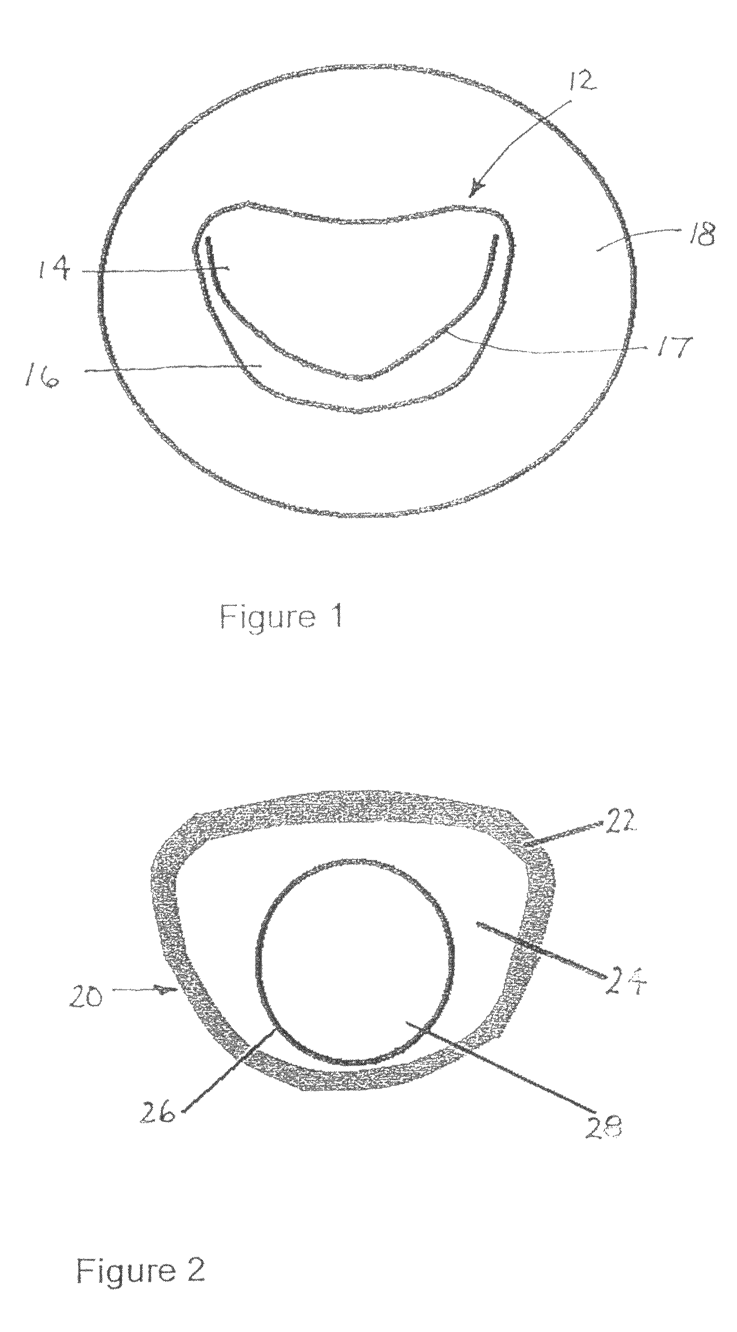
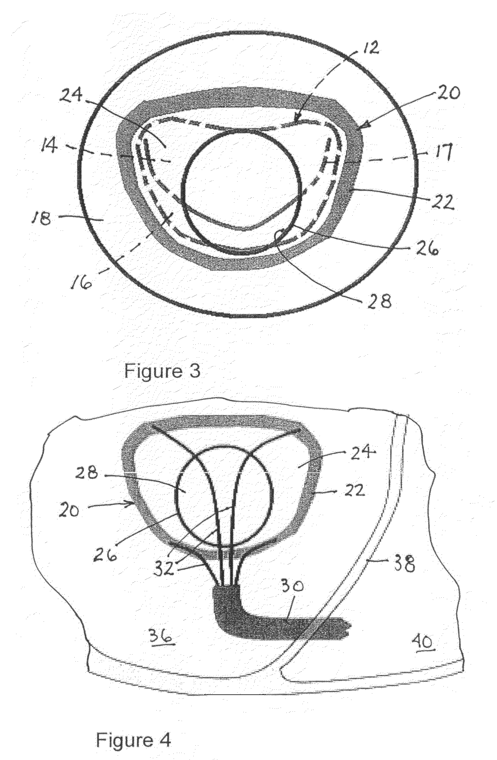
[0107]As depicted in FIG. 1, a mitral valve 12 includes a pair of leaflets or valve flaps 14 and 16 that contact one another along a generally D-shaped set of points 17 in a closed state of the valve. On the atrial side of the valve 12, leaflets are continuous with an internal wall 18 of the atrium.

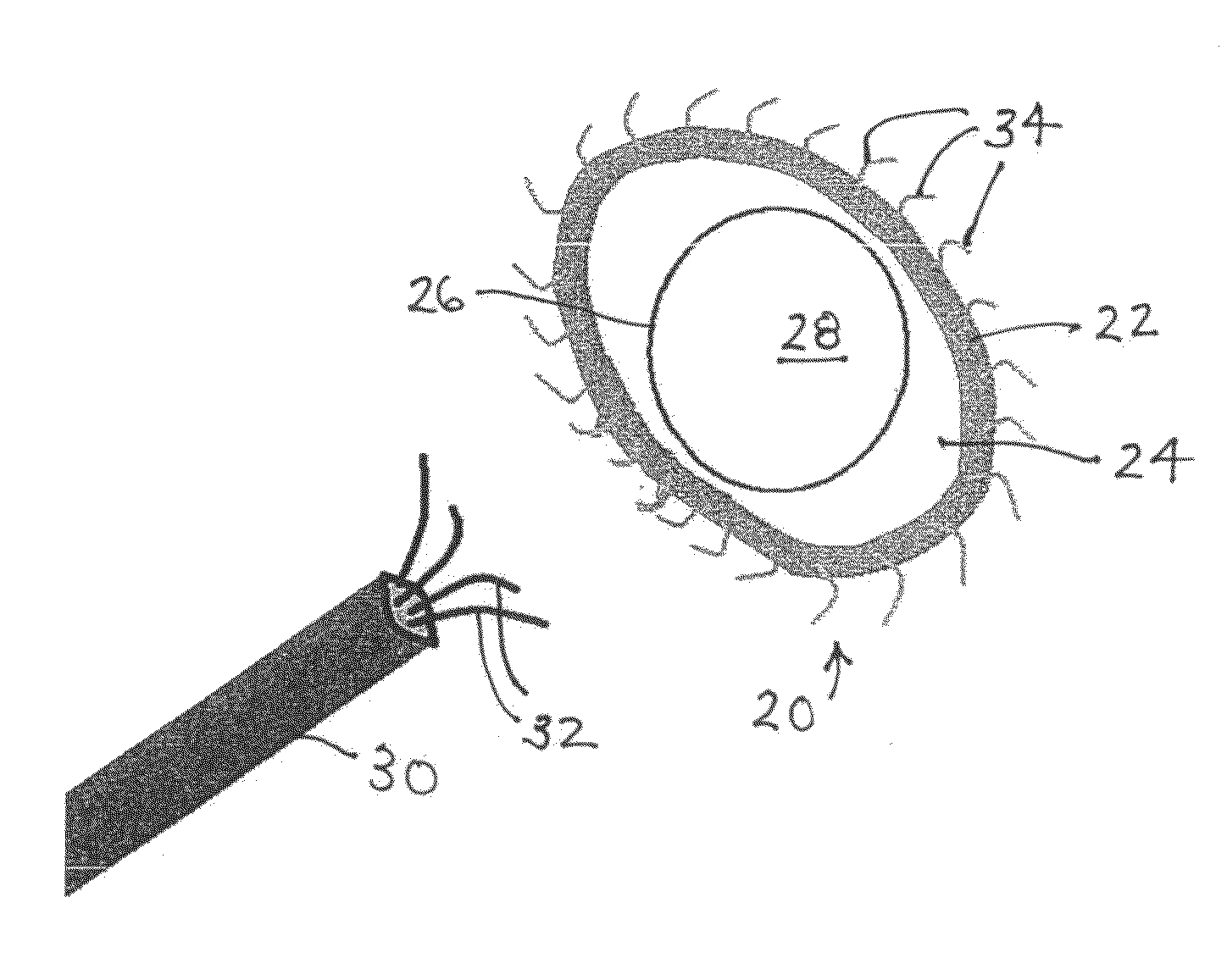
[0108]As depicted in FIG. 2, an implantable valve scaffold or mounting component 20 includes an outer margin or rim element 22, a membranous portion 24, and a generally annular inner margin or rim element 26 defining an orifice 28. Outer margin element 22 and inner margin element 26 are different from one another and spaced in their entireties from one another. Orifice 28 serves as a neo-annulus for receiving or seating a prosthetic or bio-prosthetic valve 42 (FIG. 9). It is contemplated that the valve is a modular or staple article. However, the valve may be custom designed.

[0109]It is to...


PUM


Abstract

In a surgical method for improving cardiac function, an implantable scaffold or valve support device is inserted inside a patient's heart and attached to the heart in a region about a natural mitral valve. The scaffold or valve support device defines an orifice and, after the attaching of the scaffold or valve support device to the heart, a prosthetic or bio-prosthetic valve is seated in the orifice. The scaffold or valve support device is at least indirectly secured to cordae tendenae of the heart.

Description

CROSS-REFERENCE TO RELATED APPLICATION[0001]This application claims the benefit of U.S. Provisional Patent Application No. 61 / 168,279 filed 10 Apr. 2009.FIELD OF THE INVENTION[0002]The present invention relates to medical devices and procedures, in particular related to the replacement of a heart valve, and more particularly, to a novel device for use in a novel procedure for performing a catheter-based heart valve replacement.BACKGROUND OF THE INVENTION[0003]The four valves of the human heart consist of either two or three pliable leaflets attached circumferentially to a fibrous skeletal annulus. Normally, they function to open in one portion of the cardiac cycle, either systole or diastole, (depending on the valve), causing minimal resistance to forward blood flow, but close by hinging from the annulus during the other part of the cardiac cycle, with the leaflets (either two or three) coming into central contact with each other, such that retrograde flow is inhibited.[0004]Heart v...

Claims


Application Information

Patent Timeline
Patent Type & Authority Patents(United States)
IPC IPC(8): A61F2/24A61B17/00A61B17/04
CPCA61F2/2409A61B17/0469A61F2/2427A61B2017/003A61B2017/00349A61F2/2412A61F2/2457A61F2/246A61F2250/0003A61F2250/0006A61F2/2436A61F2/2439A61B2017/00243A61B2017/0409A61B2017/0427A61B2017/0441A61F2/2418A61F2220/0008A61F2220/0016A61F2250/006A61F2/2445A61F2/2466
Inventor ANNEST, LON SUTHERLAND
Owner ANNEST LON SUTHERLAND
Why Eureka
Try Eureka