High strength and high thermal conductivity copper alloy tube and method for producing the same

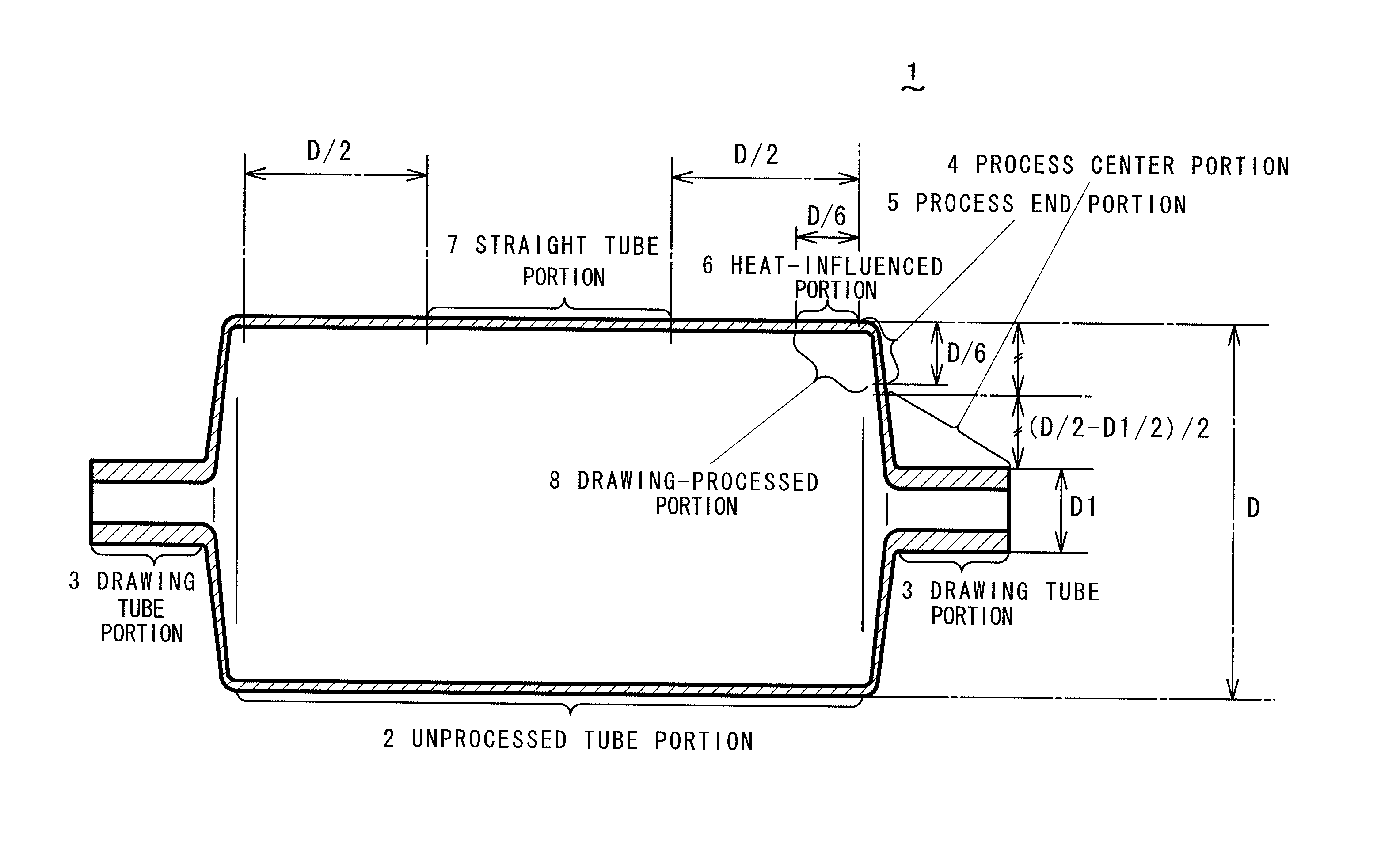
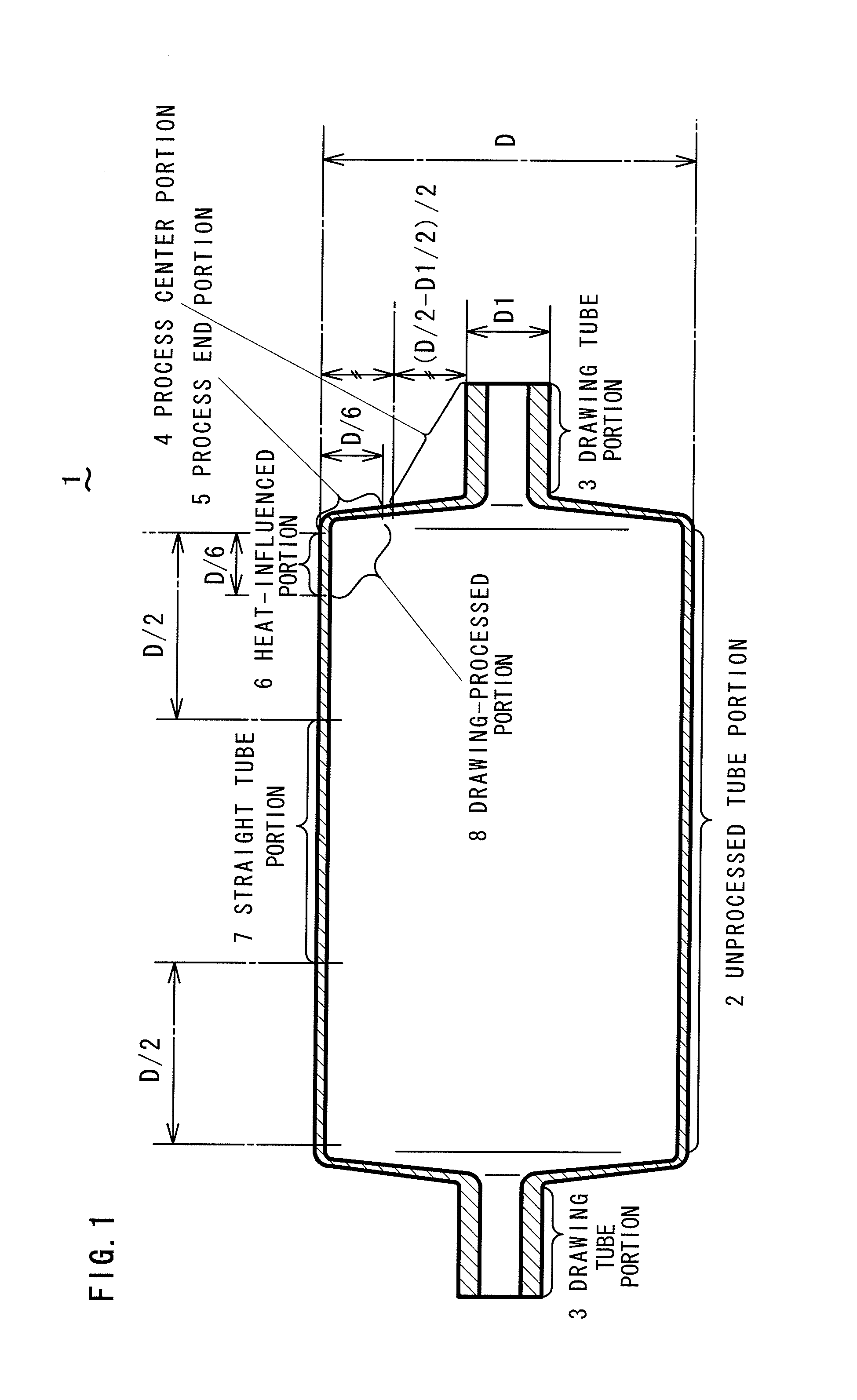
a high-temperature conductivity, copper alloy technology, applied in the direction of metal rolling arrangement, transportation and packaging, light and heating equipment, etc., can solve the problems of low pressure resistance of the process end portion b>5/b> and the heat-influenced portion b>6/b>, low productivity of drawing-processed copper alloy tubes formed in cold states, and decrease the strength. , to achieve the effect of high strength, improved thermal conductivity and high strength

Active Publication Date: 2015-03-24
MITSUBISHI SHINDOH CO LTD
View PDF47 Cites 4 Cited by
  • Summary
  • Abstract
  • Description
  • Claims
  • Application Information

AI Technical Summary

Benefits of technology

[0025]The invention has been made to solve the aforementioned problems, and an object thereof is to provide a high strength and high thermal conductivity copper alloy tube having high pressure resistance substantially without decreasing strength even when performing a drawing process, and a method for producing the same.

Problems solved by technology

However, pressure resistance of the process end portion 5 and the heat-influenced portion 6 is low, since the strength thereof is decreased by restoration and recrystallization and the thickness thereof is not increased with the large outer diameter.
When the temperature becomes 700° C. or higher even for a moment, crystal gains thereof are coarsened, thereby decreasing the strength.
However, the drawing-processed copper tube formed in a cold state has low productivity, and there is a problem in pressure resistance since the thickness of the process center portion 4 or the process end portion 5 is small.
When the thickness of the pressure-resistance and the heat-transfer vessel increases and thus the weight thereof increases, the cost also increases.
For structural reasons and to prevent vibration, a member for fixing the pressure-resistance and heat-transfer vessel needs to be strengthened, and thus the cost further increases.
Since the amount of the drawing process for producing the pressure-resistance and heat transfer vessel is increased by the increase of the thickness, the cost further increases.
A pressure-resistance and heat-transfer vessel using an inexpensive steel tube has been known, but the vessel is poor in thermal conductivity.
In addition, in the spinning process, it is difficult to the drawing process as long as the temperature does not become a high temperature at which deformation resistance of a material decreases.
For this reason, a tool is overloaded and thus durability of the tool decreases.
Such a steel tube is formed mainly by brazing or welding a press product, but reliability is low.
Since the copper alloy tube shown in Patent Document 1 is easily recrystallized at a high temperature, pressure resistance of the pressure-resistance and heat-transfer vessel processed at a high temperature after a spinning process or a brazing process is not sufficient.Patent Document 1: Japanese Patent Application Laid-Open No. 2003-268467

Method used


Image

  • High strength and high thermal conductivity copper alloy tube and method for producing the same
  • High strength and high thermal conductivity copper alloy tube and method for producing the same
  • High strength and high thermal conductivity copper alloy tube and method for producing the same

Examples


first embodiment

[0049]A high function copper tube according to a first embodiment of the invention will be described. In the invention, alloys (hereinafter, referred to as first invention alloy, second invention alloy, third invention alloy, and fourth invention alloy) having alloy compositions of the high function copper tubes according to first to fourth embodiments are provided. In the alloy compositions described in the specification, a symbol for element in parenthesis such as [Co] represents a content of the element. Invention alloy is the general term for the first to fourth invention alloys.

[0050]The first invention alloy contains Co of 0.12 to 0.32 mass % (preferably 0.13 to 0.28 mass %, more preferably 0.15 to 0.24 mass %), P of 0.042 to 0.095 mass % (preferably 0.046 to 0.079 mass %, more preferably 0.049 to 0.072 mass %), and Sn of 0.005 to 0.30 mass % (preferably 0.01 to 0.2 mass %, more preferably 0.03 to 0.16 mass %, or particularly, in the case of needing high thermal conductivity, ...

second embodiment

[0144]A high function copper tube according to a second embodiment of the invention will be described. In the embodiment, differently from the first embodiment, a pressure-resistance and heat-transfer vessel is produced by a cold drawing process such as a swaging process, “Hera-shibori”, and roll forming, instead of the spinning process.

example

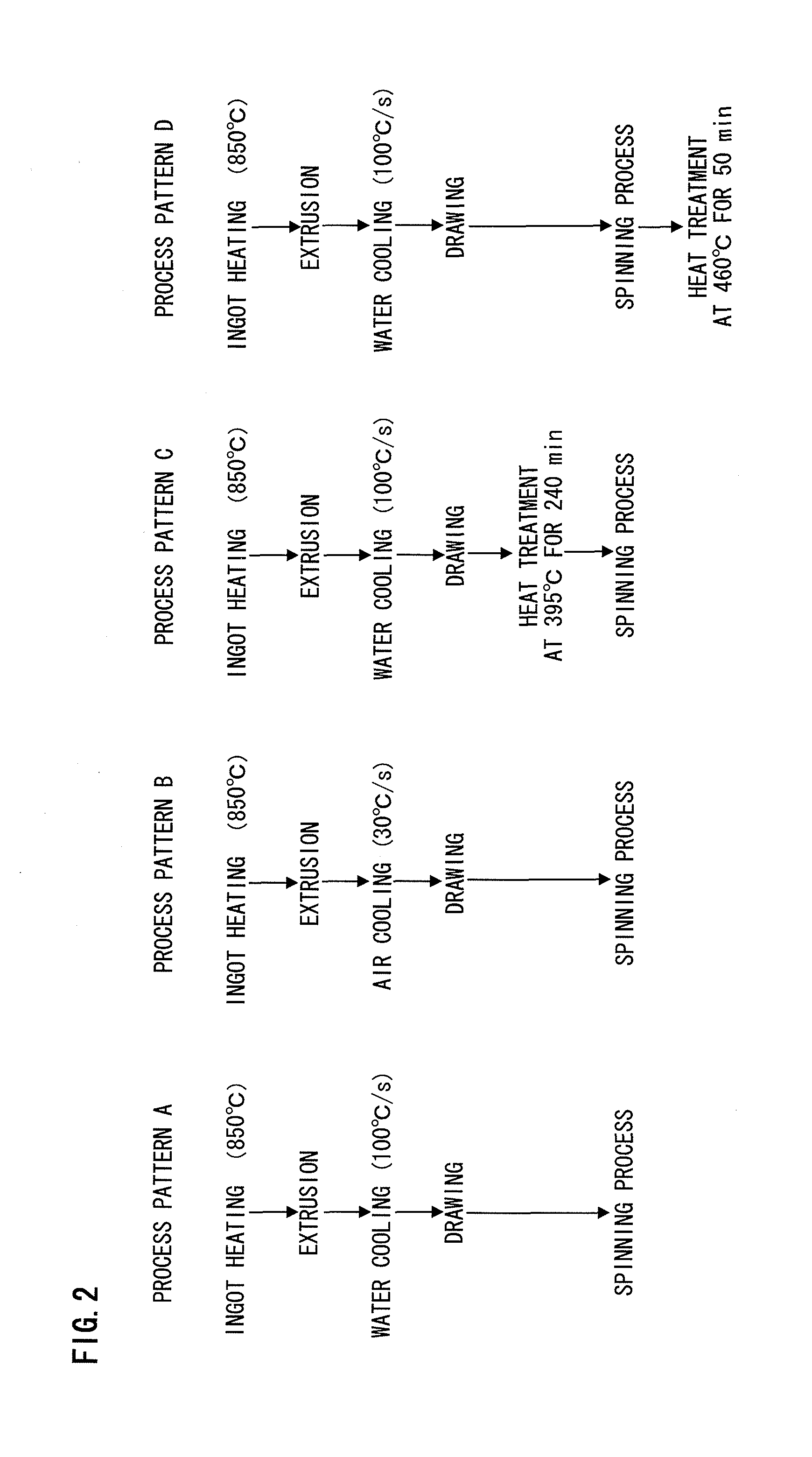
[0145]The same high function copper tubes as the example of the first embodiment were produced, and then the pressure-resistance and heat-transfer vessels were produced by the cold drawing process. Three produced pressure-resistance and heat-transfer vessels were prepared for each production condition. As for two vessels among them, one end of the drawing tube portion 3 was connected to a jig made of brass for a pressure-resistance test by phosphorus copper lead (7 mass % P—Cu), and the other end was sealed up by phosphorus copper lead. As for one of the two vessels, all properties such as metal structure, Vickers hardness, and conductivity were examined. As for the other of the two vessels, pressure resistance was examined. The vessel was not subjected to brazing, a part corresponding to the process end portion 5 and the heat-influenced portion 6 was cut with the pressure-resistance and heat-transfer vessels as it was, was immersed in salt bath heated to 700° C. for 20 seconds, was...


PUM


Abstract

A high strength and high thermal conductivity copper alloy tube contains: Co of 0.12 to 0.32 mass %; P of 0.042 to 0.095 mass %; and Sn of 0.005 to 0.30 mass %, wherein a relationship of 3.0≦([Co]−0.007) / ([P]−0.008)≦6.2 is satisfied between a content [Co] mass % of Co and a content [P] mass % of P, and the remainder includes Cu and inevitable impurities. Even when a temperature is increased by heat generated by a drawing process, a recrystallization temperature is increased by uniform precipitation of a compound of Co and P and by solid-solution of Sn. Thus, the generation of recrystallization nucleuses is delayed, thereby improving heat resistance and pressure resistance of the high strength and high thermal conductivity copper alloy tube.

Description

[0001]This is a National Phase Application in the United States of International Patent Application No. PCT / JP2008 / 70410 filed Nov. 10, 2008, which claims priority from Japanese Patent Application No. 2007-331080, filed Dec. 21, 2007. The entire disclosures of the above patent applications are hereby incorporated by reference.BACKGROUND OF THE INVENTION[0002]1. Field of the Invention[0003]The invention relates to a drawing-processed high strength and high thermal conductivity copper alloy tube and a method for producing the same.[0004]2. Description of Related Art[0005]Copper having excellent thermal conductivity has been used for tube members (hereinafter, referred to as a pressure-resistance and heat-transfer vessel in the general term) such as a header, a distribution joint, a dryer, a muffler, a filter, and an accumulator used for heat exchangers for such as a refrigerator, a freezer, an air conditioner, and a boiler, since previous times. Generally, a high strength and high the...

Claims


Application Information

Patent Timeline
Patent Type & Authority Patents(United States)
IPC IPC(8): B21C1/00C22C9/06C22F1/08B21C23/00B21C23/08C22C9/02F28F21/08
CPCC22C9/06B21C1/003B21C23/002B21C23/085C22C9/02F28F21/085C22F1/08C22C9/04Y10T428/12B21B19/00B21C23/08B21D22/14C22C9/00
Inventor OISHI, KEIICHIRO
Owner MITSUBISHI SHINDOH CO LTD
Why Eureka
Try Eureka