Supercharge Your Innovation With Domain-Expert AI Agents!

Method for the operation of a transmission device in a vehicle drive train, comprising at least one form-fitting shifting element and multiple frictionally engaged shifting elements

a transmission device and vehicle drive technology, applied in mechanical equipment, transportation and packaging, instruments, etc., can solve the problems of form-fitting shifting elements only being disconnected from the flow of power, affecting the overall efficiency of automatic transmission to an undesirable extent, and achieving the effect of avoiding the influence of shift quality

Active Publication Date: 2015-03-24
ZF FRIEDRICHSHAFEN AG
View PDF41 Cites 3 Cited by
  • Summary
  • Abstract
  • Description
  • Claims
  • Application Information

AI Technical Summary

Benefits of technology

This method improves shift quality by ensuring precise and timely disengagement of form-fitting shifting elements, reducing unwanted torque reactions and enhancing shifting comfort during gear changes.

Problems solved by technology

Frictionally engaged shifting elements in a disengaged operating state disadvantageously causes drag torques, which affect the overall efficiency of an automatic transmission to an undesirable extent.
In addition, form-fitting shifting elements that are connected in the flow of power of a transmission device with low shift forces can only be disconnected from the flow of power when they are near their load-free operating state.
If the form-fitting shifting element is disengaged by a premature or late actuation of the form-fitting shifting element, for example, there is a possibility that at least a part of the torque applied via the transmission device will be applied to the form-fitting shifting element at a predefined target moment of disengagement and the disengagement of the form-fitting shifting element in a vehicle drive train equipped with the transmission device will produce an unwanted drive train reaction as a result of the abrupt reduction in the torque applied to the form-fitting shifting element, which the driver of a vehicle that implements the vehicle drive train will perceive as an unpleasantly noticeable jolt.
Moreover, in the event of a disengagement or release attempt that is too late, wherein the transmission capability of the frictionally engaged shifting element that is to be connected is already too high, there is the possibility that the form-fitting shifting element can only be transferred into its disengaged operating state by applying undesirably high shift forces, which are caused due to high frictional forces between the inter-engaging halves of the shifting element created by tensions in the region of the transmission device.

Method used


Image

  • Method for the operation of a transmission device in a vehicle drive train, comprising at least one form-fitting shifting element and multiple frictionally engaged shifting elements
  • Method for the operation of a transmission device in a vehicle drive train, comprising at least one form-fitting shifting element and multiple frictionally engaged shifting elements
  • Method for the operation of a transmission device in a vehicle drive train, comprising at least one form-fitting shifting element and multiple frictionally engaged shifting elements

Examples


Embodiment Construction

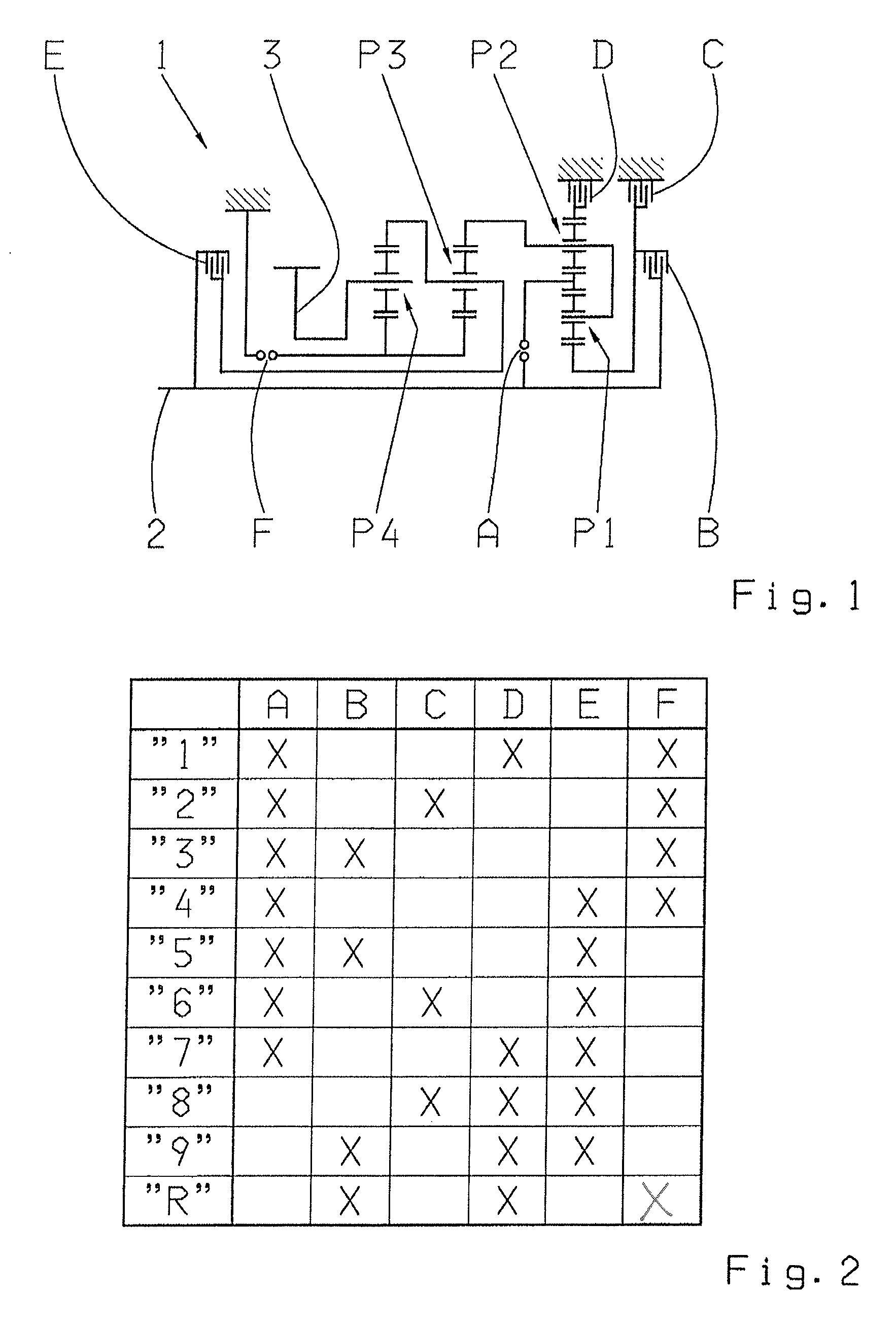
[0033]FIG. 1 shows a gear diagram of a transmission device 1 or of a multi-stage transmission, which is essentially known from the document DE 10 2008 000 429 A1. The transmission device 1 comprises a drive shaft 2 and an output shaft 3, which, when in an installed state in a vehicle, is connected to a vehicle output drive, while the drive shaft 2 is operatively connected to a drive motor.

[0034]Moreover, the transmission device 1 comprises four planetary gear sets, P1 to P4, wherein the first and the second planetary set P1, P2, which are advantageously designed as minus planetary gear sets, embody a shiftable front-mounted gear set, while the third and fourth planetary set P3 and P4 embody the main gear set. In addition, the transmission device 1 comprises six shifting elements A to F, of which the shifting elements C, D and F are designed as brakes and the shifting elements A, B and E are designed as shifting clutches.

[0035]In accordance with the shifting logic shown in detail in ...


PUM


Abstract

When a request is made to change gears, the form-fitting shifting element being disengaged, for the requested gear change, is disengaged at a predefined target disengagement moment following the target disengagement moment. When the gear is actually changed, an actual disengagement moment is determined based on when the form-fitting shifting element begins disengaging and a transmission operating state variable. If there is a deviation between the actual moment and the target moment of disengagement, then the target disengagement moment is modified by a time value, and the moment when the form-fitting shifting element begins to be actuated is shifted in time in relation to the target moment of disengagement and / or actuation of the shifting element to be connected is adjusted to a determined characteristic of the operating state of the form-fitting shifting element to be disconnected such that it is disengaged approximately at the target disengagement moment.

Description

[0001]This application is a National Stage completion of PCT / EP2011 / 069555 filed Nov. 7, 2011, which claims priority from German patent application serial no. 10 2010 063 028.4 filed Dec. 14, 2010.FIELD OF THE INVENTION[0002]The invention relates to a method for the operation of a transmission device of a vehicle drive train, comprising at least one form-fitting shifting element and multiple frictionally engaged shifting elements.BACKGROUND OF THE INVENTION[0003]A transmission device that is configured as an 8-speed multi-stage transmission having frictionally engaged shifting elements, such as lamellar clutches and multi-disk brakes, is known from the document DE 10 2005 002 337 A1. When a shifting request is made for a gear change in the transmission device, at least one frictionally engaged shifting element, which is connected in the flow of power of the transmission device in order to obtain the actual gear ratio currently selected in the transmission device, must be disconnecte...

Claims


Application Information

Patent Timeline
Patent Type & Authority Patents(United States)
IPC IPC(8): G06F7/00F16H61/04F16H61/08F16H61/68
CPCF16H61/68F16H61/08F16H61/0437F16H2061/0474F16H2200/2064F16H2306/44F16H2306/46F16H2200/2094
Inventor ARNOLD, JORGHERBETH, VALENTINEMIHATSCH, GEORG
Owner ZF FRIEDRICHSHAFEN AG
Features
  • R&D
  • Intellectual Property
  • Life Sciences
  • Materials
  • Tech Scout
  • Unparalleled Data Quality
  • Higher Quality Content
  • 60% Fewer Hallucinations
Learn More