G-arm X-ray imaging apparatus

a technology of x-ray imaging and g-arm, which is applied in the direction of electrical equipment, medical science, diagnostics, etc., can solve the problems of inconvenient operation, and inability to rotate the imaging chain. achieve the effect of greater orbital rotation angl

Inactive Publication Date: 2015-03-31
WHALE IMAGING INC
View PDF10 Cites 4 Cited by
  • Summary
  • Abstract
  • Description
  • Claims
  • Application Information

AI Technical Summary

Benefits of technology

[0014]In one embodiment, the C-arm equipment is smart and flexible, which should be attributed to the C-arm base. The C-arm base could be a floor-mounted one, a ceiling mounted one, and / or a wheeled mobile one. The common feature is that the C-arm base can provide at least the orbital rotation and the lateral rotation. Other motion degrees of freedom can also be provided. Mounting G-arm gantry and imaging chains to a C-arm base would make the G-arm equipment smarter and more flexible. G-arm equipment could have both the orbital rotation and the lateral rotation like a C-arm.
[0015]In another embodiment, two side-mounted imaging chains are introduced to the G-arm equipment. Each imaging chain contains at least one X-ray source and one receptor mounted on the opposing ends of the G-arm gantry. One imaging chain is perpendicular to another. The advantage of the perpendicular imaging chain is that radiography or fluoroscopy can be performed at both the AP&LAT positions simultaneously without repositioning the equipment. The advantage of the side-mounted imaging chain is that a greater orbital rotation angle can be obtained, without loss of patient or operation space, because the imaging chain elements do not get in the way of the rotating gantry. In this embodiment, the orbital rotation angle could be larger than the existing G-arm and C-arm equipment.
[0016]In one aspect, a bi-planar X-ray apparatus is provided. The apparatus has a support gantry, with two X-ray imaging chains attached to it. The first and second imaging chains each comprise an X-ray source, an X-ray receptor, and a collimator. The two X-ray receptors are each connected to an arm, and each arm is adjustably mounted to the support gantry. The adjustable arms allow each of the X-ray receptors to be moved between an extended position away from the gantry, to a retracted position close to the gantry. This aspect allows the X-ray apparatus, when the X-ray receptors are in an extended position to create a G-arm gantry having the bi-planar functionality and other advantages of G-arm X-ray apparatuses. Further, when the X-ray receptors of the apparatus are in a retracted position, the apparatus can operate with C-arm convenience with respect to adjustments, operation, positioning, and the like.

Problems solved by technology

Although the C-arm X-ray equipment is smart and flexible in positioning process, it is often desirable to take X-rays of a patient from both the AP & LAT positions (two perpendicular angles), in such situations, the operators have to reposition the C-arm because C-arm configurations do not allow for such perpendicular bi-planar imaging.
One disadvantage of this system is that, although the C-arms are coordinated, the imaging systems operate independently of one another.
Another disadvantage of this configuration is that the two C-arms occupy too much space, inconveniencing the operators.
One disadvantage of the system compared to C-arm system is that the imaging chain only has the orbital rotation ability, but no lateral rotation ability (can be rotated along the ring only).
While the two imaging system are mounted on the inner circumference of the G-arm gantry, at one aspect larger orbital rotation angle is obtained, but on the other aspect, as we know, the inner space of the gantry is important to both the patient and the operator, so one disadvantage of this configuration is that there is not enough operation space, especially compared to the C-arm configuration.
As with other configurations, the disadvantage is that the operation space is limited because of the two nested C-arms.

Method used


Image

  • G-arm X-ray imaging apparatus
  • G-arm X-ray imaging apparatus
  • G-arm X-ray imaging apparatus

Examples


Embodiment Construction

[0025]The detailed description set forth below in connection with the appended drawings is intended as a description of presently preferred embodiments of the invention and does not represent the only forms in which the present invention may be constructed and / or utilized. The description sets forth the functions and the sequence of steps for constructing and operating the invention in connection with the illustrated embodiments.

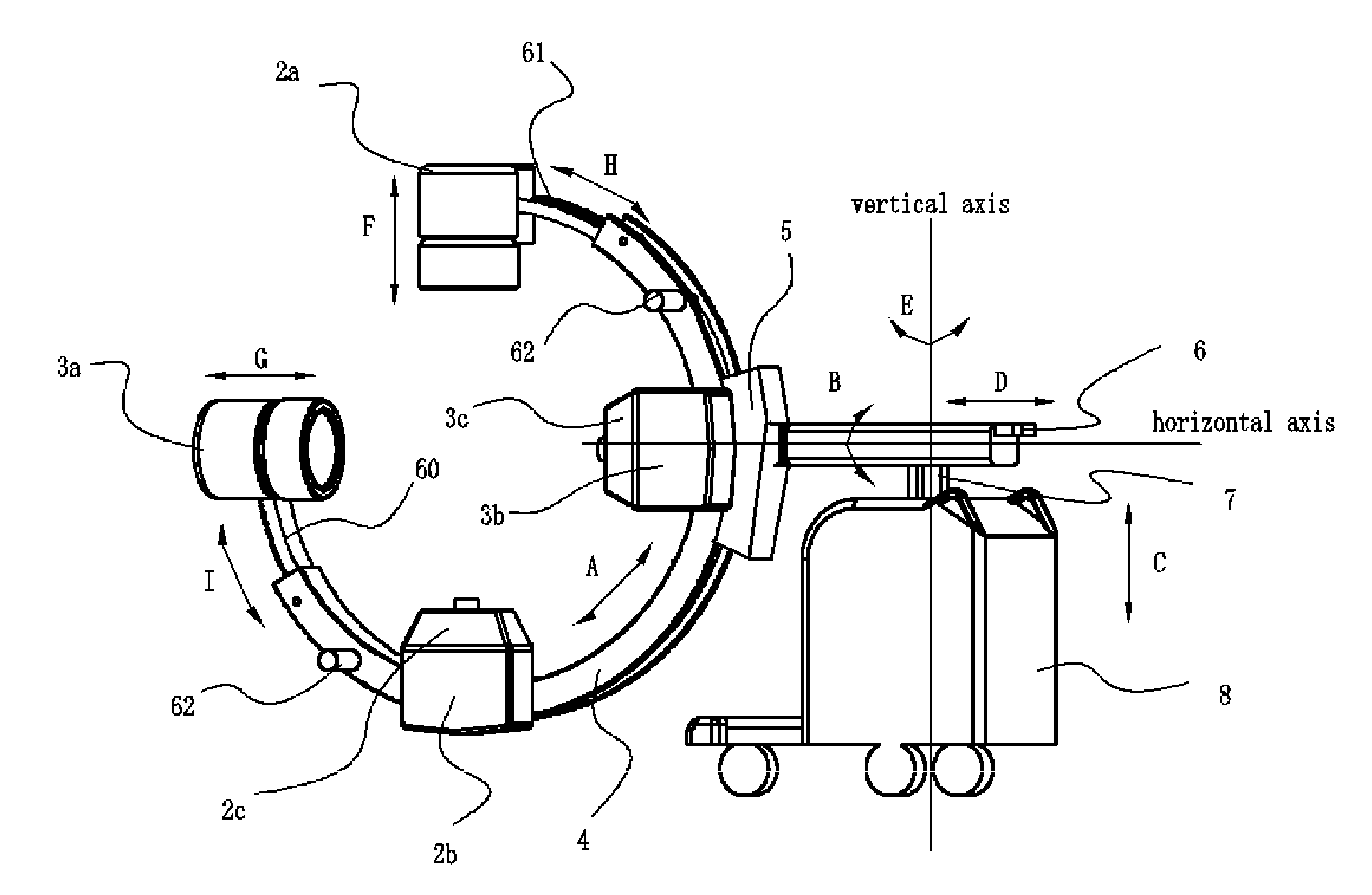
[0026]The need exists to develop a kind of bi-planar X-ray imaging apparatus with two X-ray imaging machinery formed as imaging chains, with both orbital and lateral rotation, and with a largest possible operating space. In one embodiment, the imaging chains are capable of perpendicular imaging. Meanwhile, the system should be more convenient for positioning and operation.

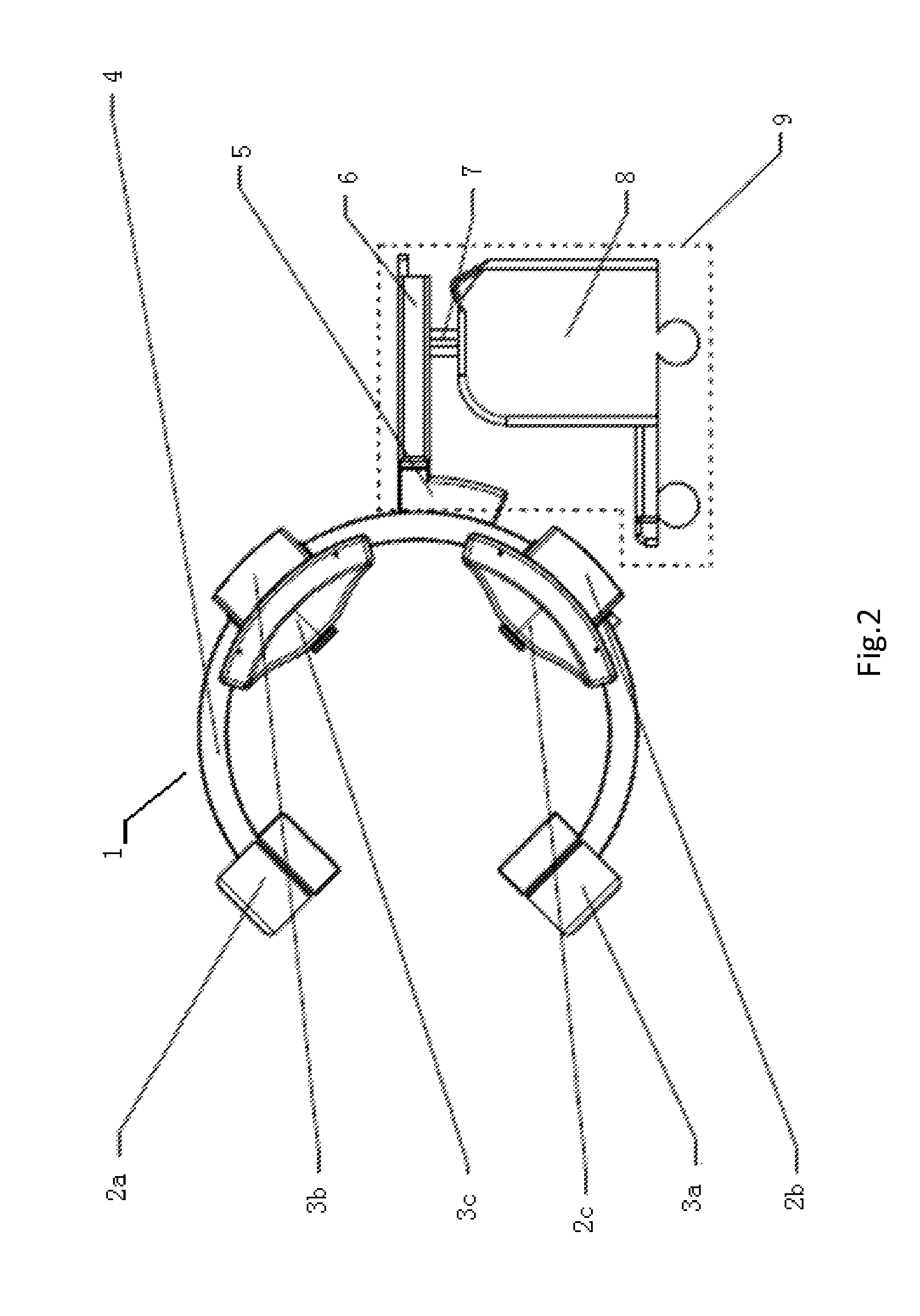
[0027]Generally, the present invention concerns an X-ray imaging apparatus having advantages of both C-shaped, G-shaped and ring-shaped arm configurations. The device consists of a gantry t...


PUM


Abstract

An X-ray imaging apparatus is provided having advantages of both C-shaped, G-shaped, and ring-shaped arm configurations. The device consists of a gantry that supports X-ray imaging machinery. The gantry is formed to allow two bi-planar X-rays to be taken simultaneously or without movement of the equipment and / or patient. The gantry is adjustable to change angles of the X-ray imaging machinery. Further, in some embodiments, the X-ray receptor portion of the X-ray imaging machinery may be positioned on retractable and extendable arms, allowing the apparatus to have a larger access opening when not in operation, but to still provide bi-planar X-ray ability when in operation.

Description

BACKGROUND OF THE INVENTION[0001]1. Field of the Invention[0002]The present invention relates generally to a G-arm X-ray imaging apparatus. More particularly, the present invention relates to a G-arm X-ray imaging apparatus having a C-arm base having bi-planar imaging chains that may be side mounted or centrally mounted.[0003]2. Description of Related Art[0004]It is often desirable to take X-rays of a patient from a number of different positions, preferably without the need for frequent repositioning of the patient. It is preferable that the X-ray apparatus not unduly encumber the space surrounding the patient to enable a physician to treat or otherwise attend to the patient without the need to repeatedly remove and replace the X-ray apparatus. C-arm X-ray equipments has been developed to meet these needs and have become well known in medical art of surgical and other interventional procedures. An example of prior art C-arm equipment is shown in FIG. 1.[0005]C-arm X-ray equipment is...

Claims


Application Information

Patent Timeline
Patent Type & Authority Patents(United States)
IPC IPC(8): H05G1/02A61B6/00
CPCA61B6/4429A61B6/4014A61B6/4405A61B6/4441A61B6/4452
Inventor ZHANG, JUNCAO, LIUWEI, SHIYUZHU, SEAN
Owner WHALE IMAGING INC
Why Eureka
Try Eureka