Automated repair method and system

a technology of automatic repair and turbomachine, which is applied in the direction of computer control, program control, instruments, etc., can solve the problems of turbomachine components, for instance, deterioration, and corrosion of turbomachine blades and vanes, and may affect the operation of the machine. , to achieve the effect of improving the service life and improving the service li

Active Publication Date: 2015-03-31
SIEMENS ENERGY GLOBAL GMBH & CO KG
View PDF19 Cites 70 Cited by
  • Summary
  • Abstract
  • Description
  • Claims
  • Application Information

AI Technical Summary

Benefits of technology

[0005]The object of the present invention is to provide a system and method for repair of a machine component that provides high accuracy and less man-power intensive as compared to the existing process described above.
[0008]In one embodiment, numerically controlling said machining includes generating a machining path in response to identifying a position of said damaged portion on the said first geometry of the component, based on a received user input. This allows the user or worker to define the areas on the component where damages have occurred on the basis of the delivery guidelines.
[0010]In an exemplary embodiment, said deposition comprises a process of laser powder cladding. This allows good dimensional control of the welding seam and provides an accurately controllable energy input which permits low heat input and produces small heat affected zones.
[0019]The position of openings on the component is thus accurately captured in the geometry of the component before the welding process.

Problems solved by technology

Metallic machine components may be subject to deterioration resulting from use.
Turbomachine components, for instance, deteriorate due to mechanical forces, as well as wear due to friction, erosion and corrosion from use in the fluid medium.
In particular, turbomachine blades and vanes experience erosion wear on their leading and trailing edges during operation.
This progressive deterioration of the blades and vanes reduces the efficiency of the turbomachine.
Again, such a process is time taking, involves high costs, is manpower intensive and may not be accurate.

Method used


Image

  • Automated repair method and system
  • Automated repair method and system
  • Automated repair method and system

Examples


Embodiment Construction

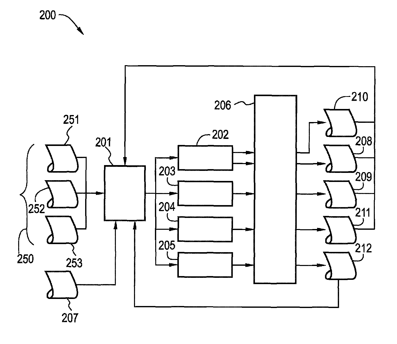
[0031]The present invention thus provides an automated process for weld repairing a damaged portion of a machine component. The present invention may be used particularly, though not exclusively, for automated repair of a blade or vane of a turbomachine. Hence it should be appreciated that although the embodiments illustrated hereinafter refer particularly to a hollow air cooled blade used in the turbine section of a gas turbine engine, the present invention is equally applicable for repair of other components, such as stationary vanes, or indeed repair of any other metallic machine component.

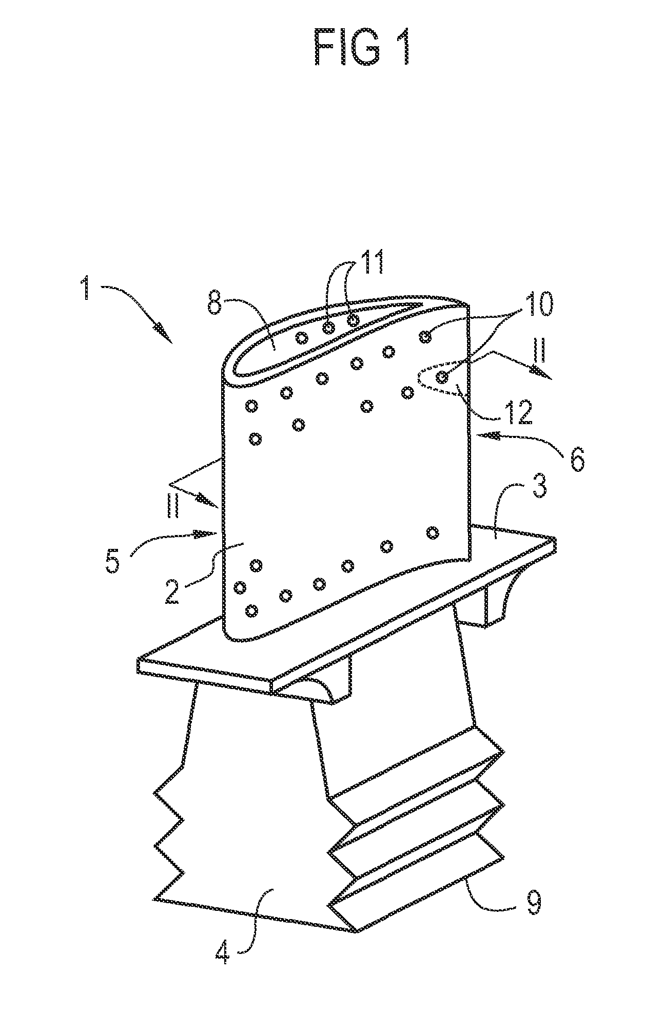
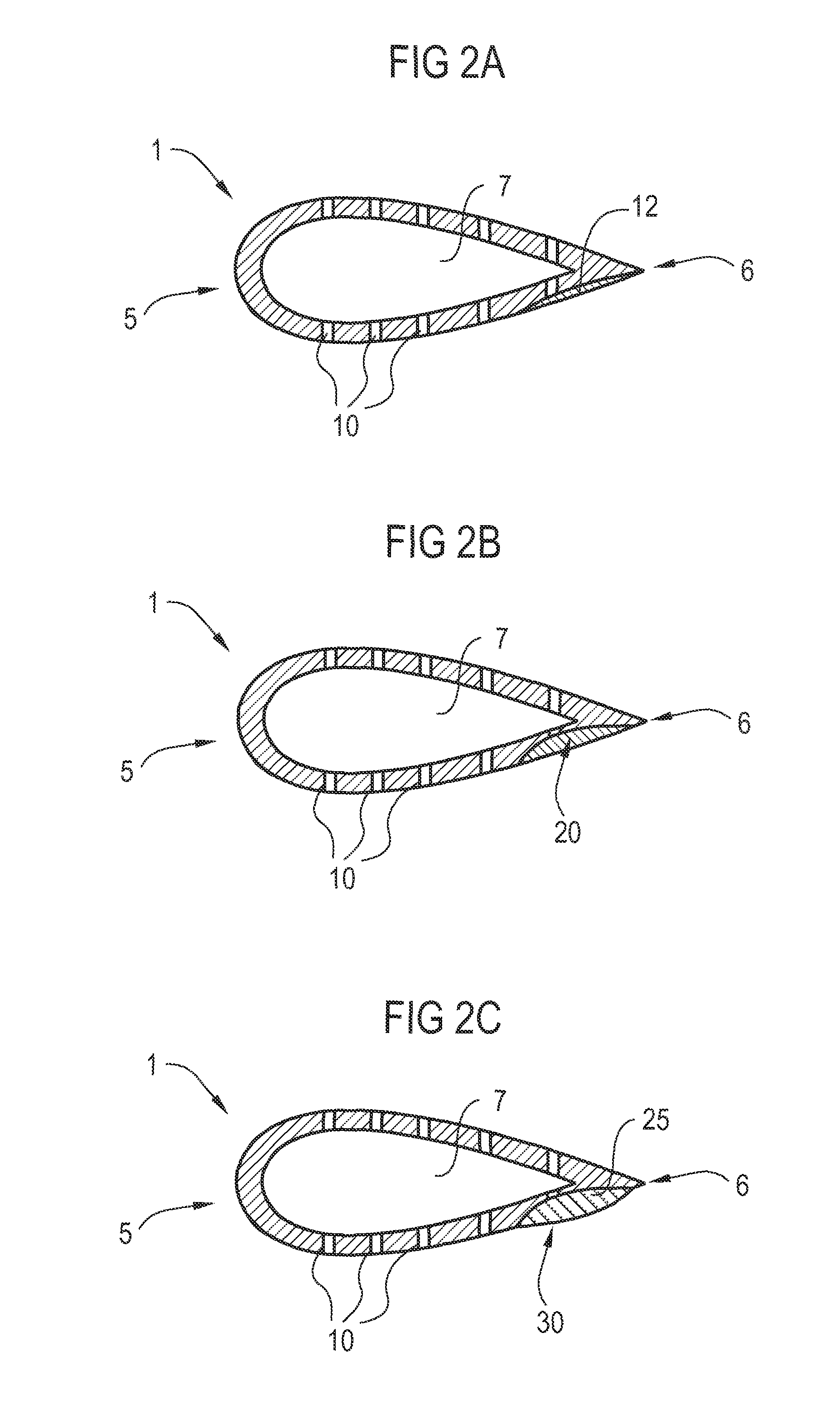
[0032]Referring to FIG. 1 is illustrated a structure of a turbine blade 1, which is to be repaired according to an example embodiment of the present invention. The structure of the blade 1 may be better illustrated also referring to FIG. 2A, which is a cross-sectional view of a section II-II of the blade 1.

[0033]The blade 1 has an airfoil portion 2, a platform portion 3 and a root portion 4 for...


PUM

PropertyMeasurementUnit
mechanical forcesaaaaaaaaaa
frictionaaaaaaaaaa
corrosionaaaaaaaaaa

Abstract

A method and system for automated repair of a machine component is provided. According to the proposed method, a first geometry of the component, including a damaged portion of the component, is digitalized. A trough is then machined over the damaged portion of the component. The machining is numerically controlled using digitalized geometrical data of the first geometry of the component. A second geometry of the component is then digitalized subsequent to the machining, the second geometry including the trough. Subsequently, a material is deposited over the trough. The deposition of the material is numerically controlled digitalized geometrical data of the second geometry of the component.

Description

CROSS REFERENCE TO RELATED APPLICATIONS[0001]This application is the US National Stage of International Application No. PCT / EP2010 / 061893, filed Aug. 16, 2010 and claims the benefit thereof. The International Application claims the benefits of European Patent Office application No. 09010737 EP filed Aug. 20, 2009. All of the applications are incorporated by reference herein in their entirety.FIELD OF INVENTION[0002]The present invention relates to automated repair of machine components. The present invention relates particularly, though not exclusively to automated repairing of a turbomachine component, such as a blade or a vane.BACKGROUND OF INVENTION[0003]Metallic machine components may be subject to deterioration resulting from use. Turbomachine components, for instance, deteriorate due to mechanical forces, as well as wear due to friction, erosion and corrosion from use in the fluid medium. In particular, turbomachine blades and vanes experience erosion wear on their leading and...

Claims


Application Information

Patent Timeline
Patent Type & Authority Patents(United States)
IPC IPC(8): G06F19/00B23K26/34B23P6/00F01D5/00G01N21/91G05B19/4099
CPCB23P6/007F01D5/005G05B19/4099B23K26/345G05B2219/32228F05D2230/30F05D2230/10G01N21/91B23K26/342G05B2219/37047G05B2219/45147B23K26/34B23P6/00F01D5/00
Inventor MELZER-JOKISCH, TORSTENTHOMAIDIS, DIMITRIOSWILKENHONER, ROLF
Owner SIEMENS ENERGY GLOBAL GMBH & CO KG
Why Eureka
Try Eureka