
Fixture for retaining an end of a member

a technology for fixing parts and fixing parts, which is applied in the direction of load securing, candle holders, lighting support devices, etc., can solve the problems of relative heavyness and difficulty in handling of locking elements, limited flexibility in use of known fixtures, and inability to correct the positioning of holes in locking elements, etc., to achieve the effect of simple and convenient assembly of members

Active Publication Date: 2015-04-07
ELEVATORRA IP APS
View PDF13 Cites 6 Cited by
  • Summary
  • Abstract
  • Description
  • Claims
  • Application Information

AI Technical Summary

Benefits of technology

The present invention provides a fixture that can hold members of different sizes and hole patterns, and allows for quicker arrangement of the member. The fixture includes a simpler and cheaper upper locking device. Additionally, the invention introduces a twist lock that securely connects two further connection devices, providing a stable connection between parts. This twist lock is mainly oriented vertically, making it easy to assemble and disassemble.

Problems solved by technology

The locking elements are naturally manufactured of high performance steel, and the locking elements are thus relative heavy and difficult to handle for the workers who are intended to secure the end of the member to the control / retaining means.
The known fixture has thus a certain, but still limited flexibility in use, understood in that way, that the limits for displacement and pivoting of the locking elements sets the limits for which diameters and hole patterns the fixture the fixture is useable for.
Further, the work with the correct positioning of the holes in the locking elements might be considerably time consuming.
Under heavy cross oriented force impacts on the member, this leads to a very hard load on the threaded rod, which demands for large strength requirements to as well the middle column, as to the threaded rod and its anchoring in the column, which results in that it will be relatively costly.

Method used


Image

  • Fixture for retaining an end of a member
  • Fixture for retaining an end of a member
  • Fixture for retaining an end of a member

Examples


Embodiment Construction

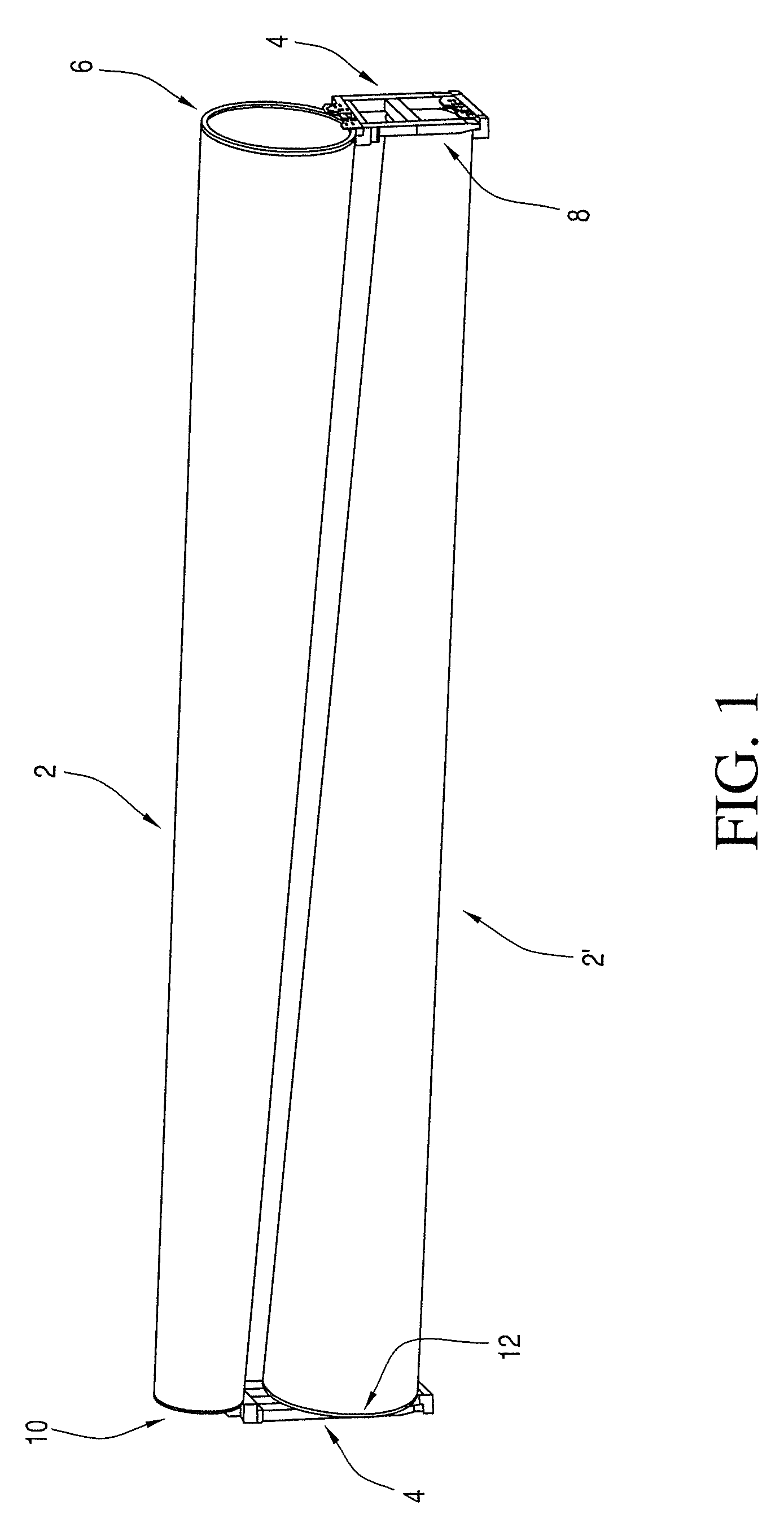
[0066]FIG. 1 shows a perspective view of a first and a second wind turbine tower section 2, 2′ arranged one above the other in fixtures 4 according to the invention. As it can be seen, the tower sections have a conical shape, and are arranged so that the end 6 with the largest diameter of one section is arranged above the end 8 with the minor diameter of the other section 2′, and the end 10 with the minor diameter of the first section 2 is arranged above the end 12 with the largest diameter of the other section 2′.

[0067]In the following, there is for the sake of clarity used the denotation “tower section” for members suited to be secured by using the fixture according to the invention. However, the members may as well comprise a wing for wind turbine mill, or a hub for a wind turbine mill so that the term tower section should be construed as encompassing such members as well.

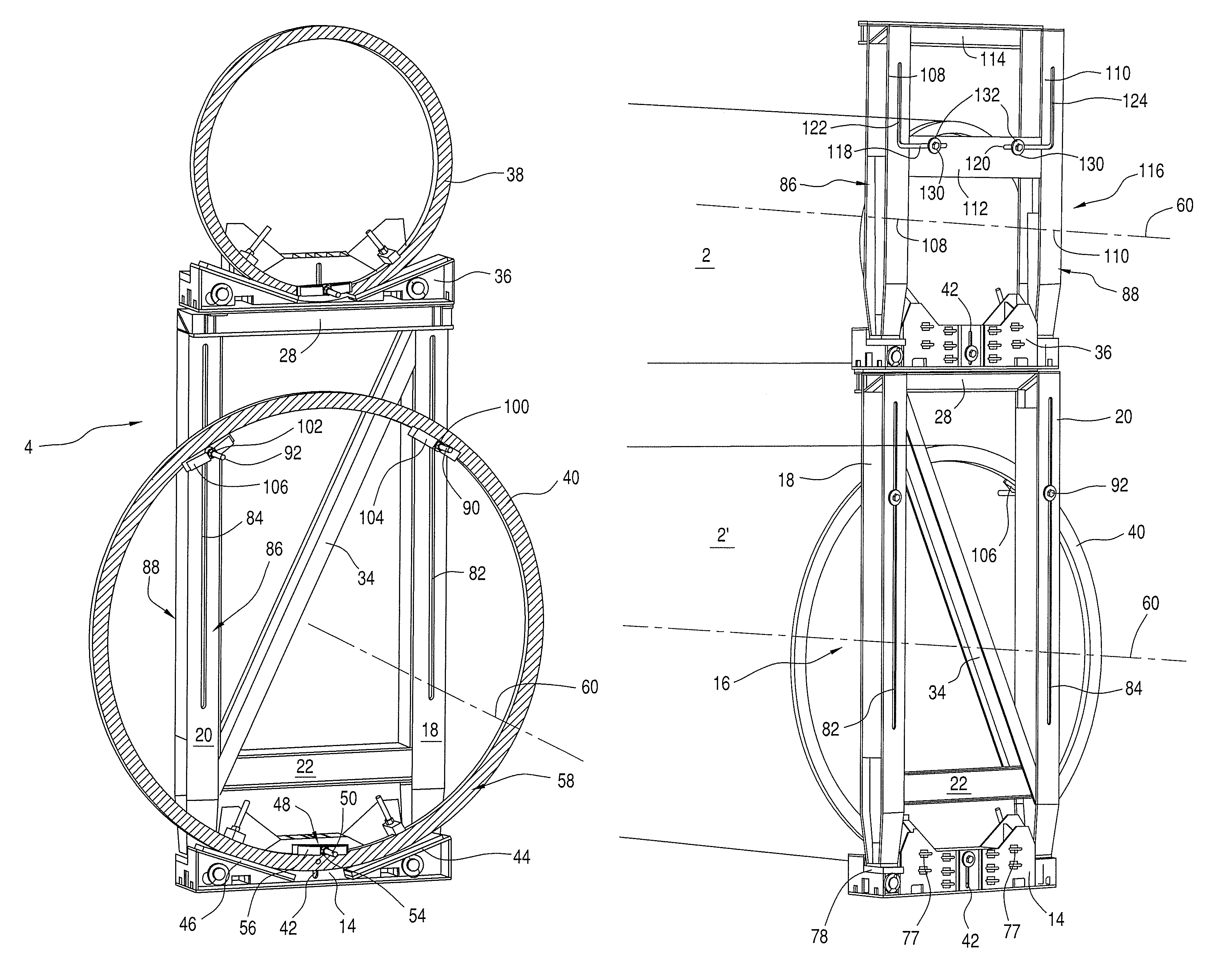
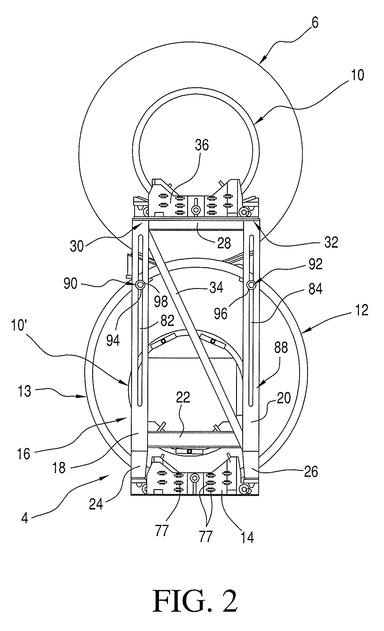
[0068]FIG. 2 is view by the ends 10, 10′ of the tower sections 2, 2′, of a first embodiment of a fixture 4 ac...


PUM


Abstract

A fixture for attachment of an end of a member, such as a wind turbine tower section, blade or hub for a wind turbine characteristically has an end flange. To enable clamping while being able to compensate for different hole patterns in the flanges, by the invention, the fixture provides for retaining of ends of members with flanges, regardless of flange diameter and hole patterns, and which is also quickly and easily installed. Additionally, it is possible to firmly clamp the flange end to upstanding frame parts of the fixture with fastening elements, thereby providing a stable connection between a console of the fixture and the upstanding frame parts.

Description

BACKGROUND OF THE INVENTION[0001]1. Field of the Invention[0002]The present invention relates to a fixture for retaining an end of a member, such as a section of a windmill tower, a blade for a windmill, or a hub for a wind mill turbine, the fixture comprising an axial control / retaining means in relation to the longitudinal axis of the member in form of a first lower console for preventing of a relative horizontal displacement between the end of the member and the fixture in a direction perpendicular to the end of the member in use, the console further including cross-positioning means for positioning the end of the member in relation to the fixture during fastening of the fixture to the end of the member in relation to a horizontal oriented direction parallel to the end of the member in use, and cross-axial holding means for preventing of a relative displacement between the end of the member and the fixture in a direction across of the longitudinal axis of the member, first connect...

Claims


Application Information

Patent Timeline
Patent Type & Authority Patents(United States)
IPC IPC(8): B60P7/12F03D1/00F03D11/00
CPCF03D1/005F03D11/00Y02E10/722F03D80/00F03D13/40Y10T403/7062F03D80/50Y02E10/72Y02E10/70F03D13/20
Inventor FENGER, PER E
Owner ELEVATORRA IP APS
Learn More