
Vascular prosthetic delivery device and method of use

a prosthetic and vascular technology, applied in the field of vascular prosthetic delivery devices and methods of use, can solve the problems of physician precise control, aortic aneurysm treatment remains a challenge, etc., and achieve the effect of minimizing potential disruption increasing the control of the movement of the vascular prosthesis

Active Publication Date: 2015-04-07
BOLTON MEDICAL INC
View PDF552 Cites 80 Cited by
  • Summary
  • Abstract
  • Description
  • Claims
  • Application Information

AI Technical Summary

Benefits of technology

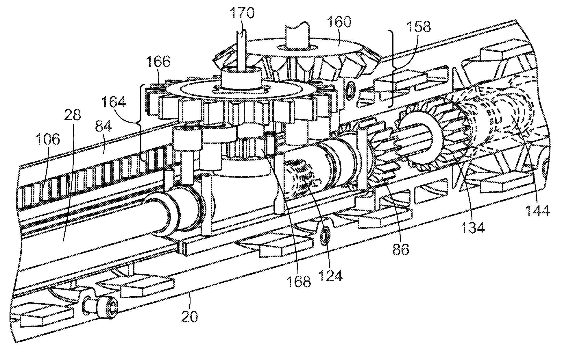
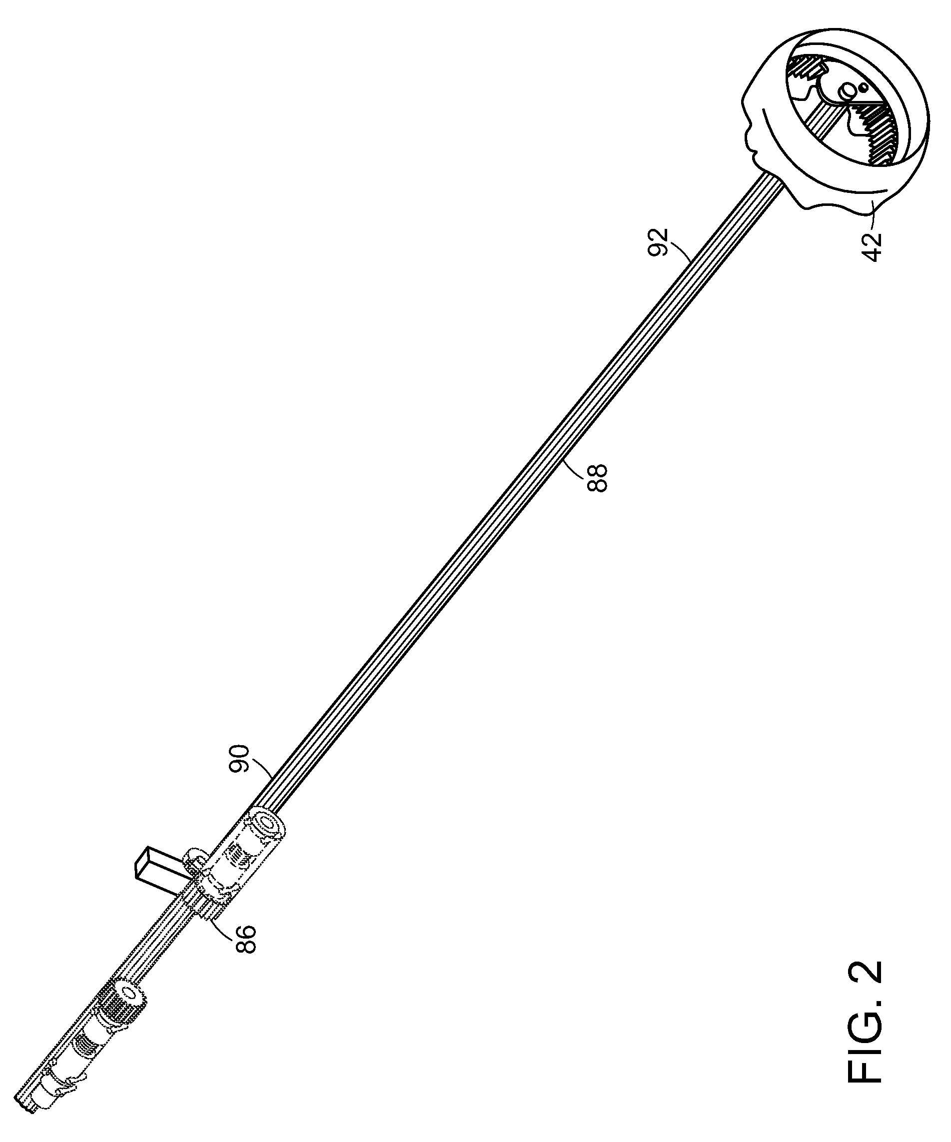
[0007]Another embodiment of the delivery device of the invention includes a distal grip at the distal end of the handle body, and the locking mechanism includes a shifting knob, a drive shaft, a drive gear and a first locking component. The shifting knob is located at the distal grip and is rotatable about the handle body and defines teeth along the inside of the shifting knob that move transversely to the major longitudinal axis of the handle body when the shifting knob is rotated about the handle body. The locking mechanism has at least two fixed positions relative to the handle body. The drive shaft has a proximal end and a distal end, wherein the distal end defines teeth that engage directly or indirectly, the teeth of the shifting knob, and extend along a major longitudinal axis of the driveshaft. The drive gear is along the drive shaft and defines teeth that engage, directly or indirectly, the teeth along the drive shaft, whereby the shifting knob is engaged with the drive gear at all positions of the shifting knob. The first locking component extends about the push rod and is linked to the proximal handle and the drive gear, whereby, in a first position of the shifting knob, the first locking component engages the proximal handle with the push rod, and rotation of the shifting knob from the first position to a second position causes rotation of the drive shaft which, in turn, causes rotation of the drive gear and disengagement of the first locking component from the push rod, thereby allowing independent movement of the delivery catheter along the longitudinal axis of the handle body relative to the push rod when the proximal handle is moved along major longitudinal axis of the handle body.
[0008]In another embodiment of the invention, the locking mechanism further includes a second locking component. The second locking component extends about the push rod, is fixed to the handle body, and is linked to the shifting knob through the drive shaft, whereby rotation of the shifting knob from the first position to the second position causes engagement between the handle body and the push rod, thereby preventing longitudinal movement of the push rod relative to the handle body when the proximal handle is moved along the major longitudinal axis.
[0012]The delivery device and method of its use of the invention have many advantages. For example, rotation of the proximal handle to thereby advance the push rod and a vascular prosthesis at the end of the push rod provides increased control over movement of the vascular prosthesis during implantation at a treatment site. Further, selective engagement of the proximal handle and the push rod enables disengagement of the proximal handle from the push rod to thereby provide for controlled refraction of a delivery sheath from the vascular prosthesis by rotation of the proximal handle in an opposite direction to that which is employed to advance the vascular prosthesis to the treatment site. In addition, an actuator of the delivery device enables selective disengagement of the proximal handle from the handle body, whereby the proximal handle can be moved along the handle body without rotation of the proximal handle, thereby providing another degree of freedom of movement of the vascular prosthesis during advancement of the vascular prosthesis to the treatment site and during retraction of the delivery sheath from the prosthesis once the prosthesis has been advanced to the treatment site. The delivery device of the invention also has the advantage of causing engagement of the push rod with the handle body upon disengagement of the proximal handle from the push rod, thereby enabling withdrawal of the delivery sheath from the vascular prosthesis without entrainment of the vascular prosthesis while the delivery sheath is being retracted from the vascular prosthesis by movement of the proximal handle. Further, the apex delivery device is controllable at a proximal end of the push rod and guidewire catheter, thereby enabling selective release of a proximal end of the vascular prosthesis at the treatment site while remaining components of the delivery device remain stationary. In addition, the push rod can be disengaged from both the handle body and the proximal handle, thereby enabling refraction of the push rod, guidewire catheter and apex delivery device from within the vascular prosthesis once it has been implanted at the delivery device, thereby minimizing potential disruption of the vascular prosthesis once it has been implanted.

Problems solved by technology

An aortic aneurysm is an enlargement or bulge in a section of the aorta, which can be life-threatening.
Treatment of aortic aneurysms remain a challenge.
Currently, endovascular delivery devices have limitations on the precise control that the physician has in placement of the graft at the site of the aneurysm.

Method used


Image

  • Vascular prosthetic delivery device and method of use
  • Vascular prosthetic delivery device and method of use
  • Vascular prosthetic delivery device and method of use

Examples


Embodiment Construction

[0055]While this invention has been particularly shown and described with references to example embodiments thereof, it will be understood by those skilled in the art that various changes in form and details may be made therein without departing from the scope of the invention encompassed by the appended claims.

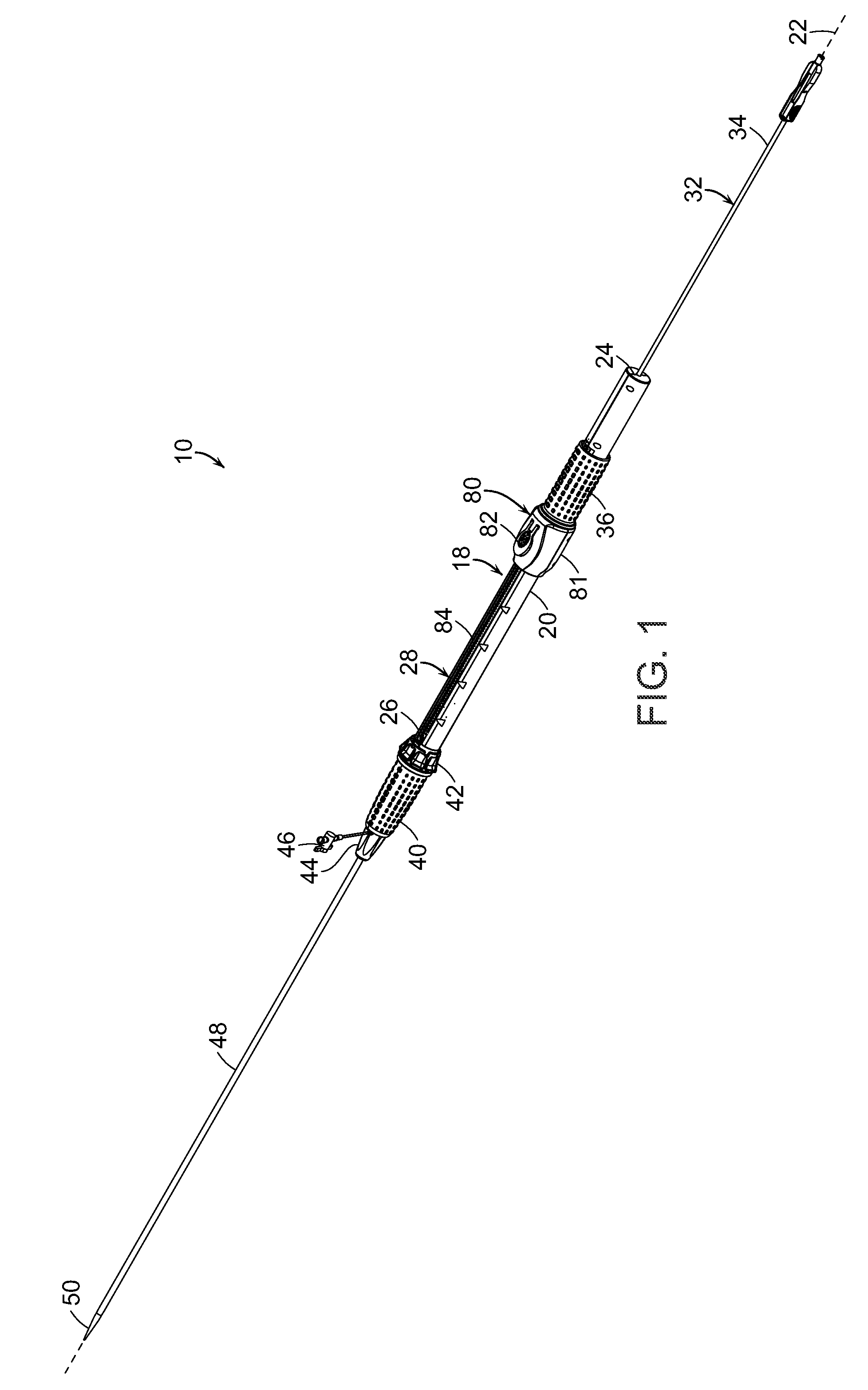
[0056]One embodiment, of the delivery device 10 of the invention is shown in FIG. 1. Delivery device 10 includes guidewire catheter 12 (FIGS. 10, 11) having a proximal end and a distal end. “Proximal,” as a term employed herein with reference to the delivery device and its components, means relatively close to the surgeon operating the delivery device. “Distal,” as a term employed herein with reference to the delivery device and its components, means relatively distal from the surgeon operating the delivery device. “Proximal,” as a term employed herein with reference to the prosthesis, stent-graft and components, means relatively close to the heart of the patient. “Distal,” a...


PUM


Abstract

A delivery device includes a guidewire catheter and a delivery assembly extending about the guidewire catheter. The delivery assembly includes a locking mechanism that selectively engages a proximal handle of the delivery assembly with a push rod to which a vascular prosthesis is directly or indirectly attached. When an actuator selectively disengages the proximal handle from the handle body, rotation of the proximal handle is independent of longitudinal movement of the vascular prosthesis relative to the handle body, whereby the proximal handle can be moved along the handle body with rotation.

Description

RELATED APPLICATION[0001]This application claims the benefit of U.S. Provisional Application No. 61 / 623,235, filed on Apr. 12, 2012. The entire teaching of the above application is incorporated herein by reference.BACKGROUND OF THE INVENTION[0002]An aortic aneurysm is an enlargement or bulge in a section of the aorta, which can be life-threatening. Treatment of aortic aneurysms remain a challenge. Endovascular repair has become a viable alternative to open repair of an aortic aneurysm. An endovascular approach results in insertion of an endovascular graft to exclude the aneurysm sac from blood flow. Once in place, the endovascular graft is expanded to create a new path for blood flow. The endovascular graft remains inside the aorta permanently through the use of a metal stent creating a tight fit and seal against the wall of the aorta. Currently, endovascular delivery devices have limitations on the precise control that the physician has in placement of the graft at the site of the ...

Claims


Application Information

Patent Timeline
Patent Type & Authority Patents(United States)
IPC IPC(8): A61F2/06A61F2/24A61F2/95A61F2/966
CPCA61F2/95A61F2/966A61F2002/9517A61F2002/9665A61F2/9517A61F2/91
Inventor ARBEFEUILLE, SAMUELCHRISTIAN, FLETCHERCANNING, JOHN C.
Owner BOLTON MEDICAL INC
Learn More