Electrical connector with hybrid shield

a hybrid shield and connector technology, applied in the direction of coupling device connection, line/current collector details, coupling protective earth/shield arrangement, etc., can solve the problems of electrical interference between adjacent signal conductors, increased possibility of electrical noise generation in the connector, and generally smaller electronic systems. , to achieve the effect of not compromising the mechanical integrity of the connector

Active Publication Date: 2015-04-14
AMPHENOL CORP
View PDF181 Cites 93 Cited by
  • Summary
  • Abstract
  • Description
  • Claims
  • Application Information

AI Technical Summary

Benefits of technology

[0011]In some embodiments, the lossy member is combined with regions of conductive material. The combined lossy member and conductive regions may be positioned adjacent to conductive elements acting as signal conductors in an electrical connector. The combined lossy and conductive materials, for example, may be positioned inside a connector housing. The position and amount of lossy and / or conductive material may be selected to provide a desired reduction of crosstalk in a desired frequency range without an undesired change in impedance of the conductive elements.
[0012]In some embodiments, the combined lossy and conductive material may be thin enough to be positioned in areas of a connector in which space is limited by mechanical constraints. Nonetheless, the combined lossy and conductive material is thin enough that the mechanical integrity of the connector is not compromised. Moreover, the combined lossy and conductive material need not be connected to a ground, enabling the combined lossy and conductive material to be used in more places within an interconnection system relative to a traditional shield.
[0016]In further embodiments, the surface area of the conductive material may be less than the surface area of the lossy material. Such a configuration may increase the frequencies at which electromagnetic energy, reaching the conductive regions, resonates in regions between adjacent conductive regions within an electrical connector. Though reducing the amount of conductive material may reduce the amount of shielding provided, the conductive material may be disposed in a pattern that positions the conductive material such that, in combination with the lossy material, an effective shield is provided.

Problems solved by technology

Electronic systems have generally become smaller, faster and functionally more complex.
One of the difficulties in making a high density, high speed connector is that electrical conductors in the connector can be so close that there can be electrical interference between adjacent signal conductors.
As signal frequencies increase, there is a greater possibility of electrical noise being generated in the connector in forms such as reflections, crosstalk and electromagnetic radiation.

Method used


Image

  • Electrical connector with hybrid shield
  • Electrical connector with hybrid shield
  • Electrical connector with hybrid shield

Examples


Embodiment Construction

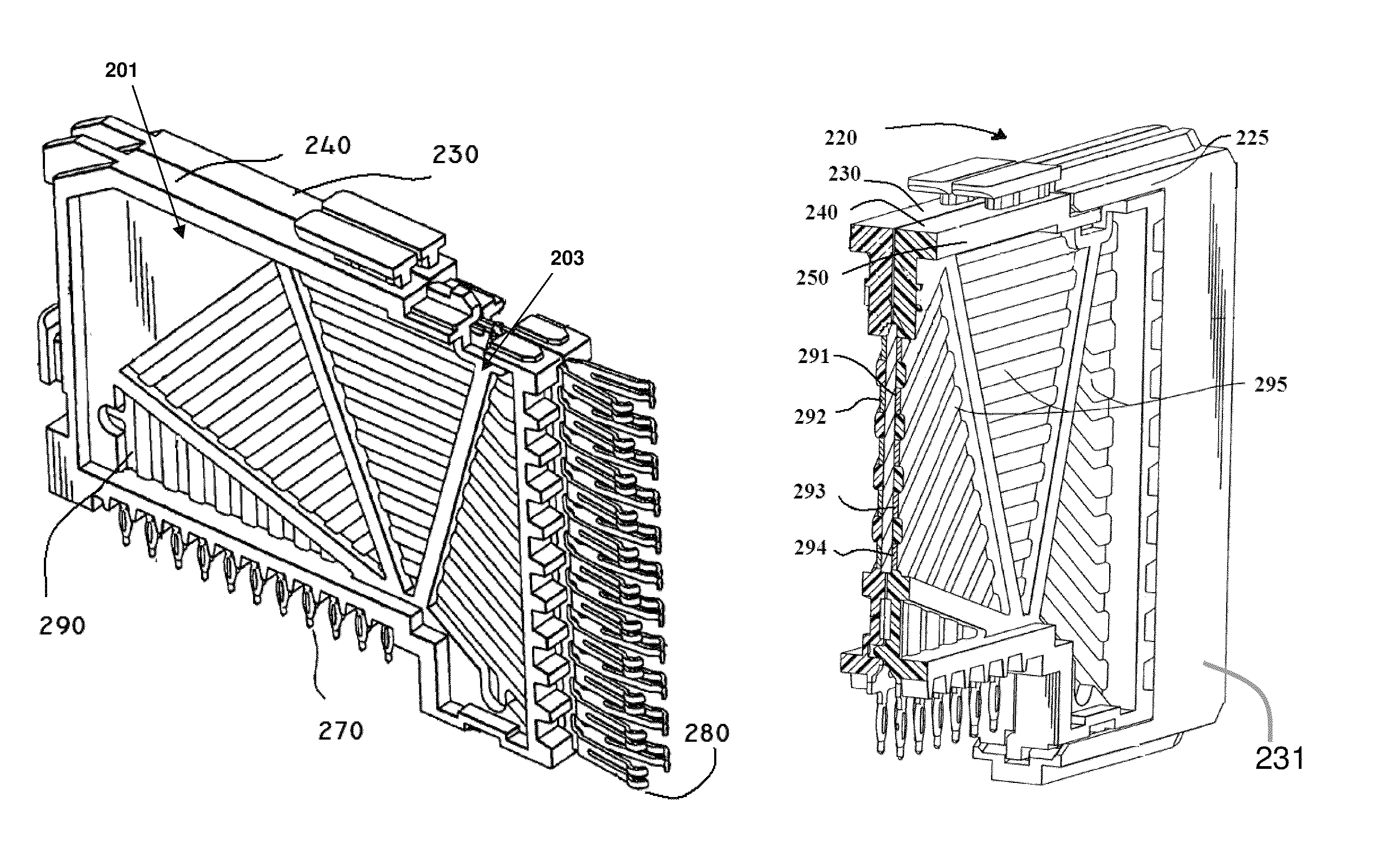
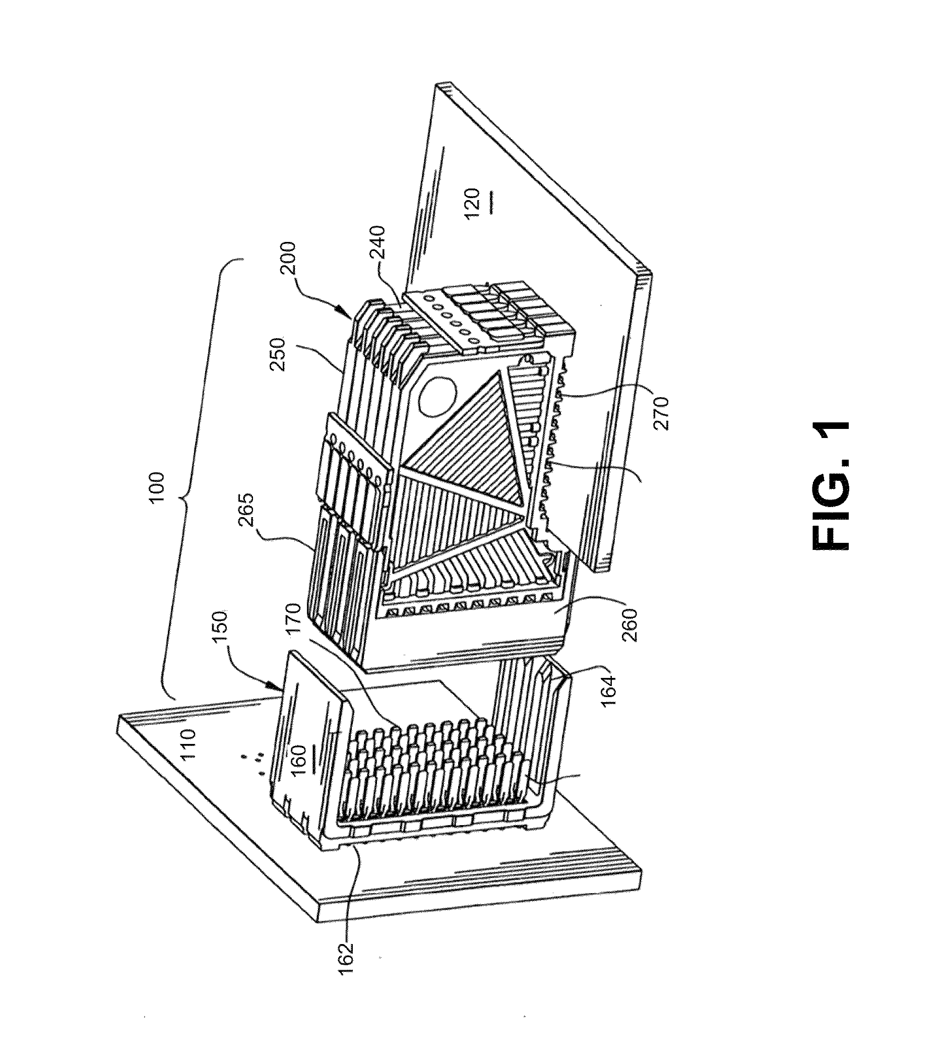
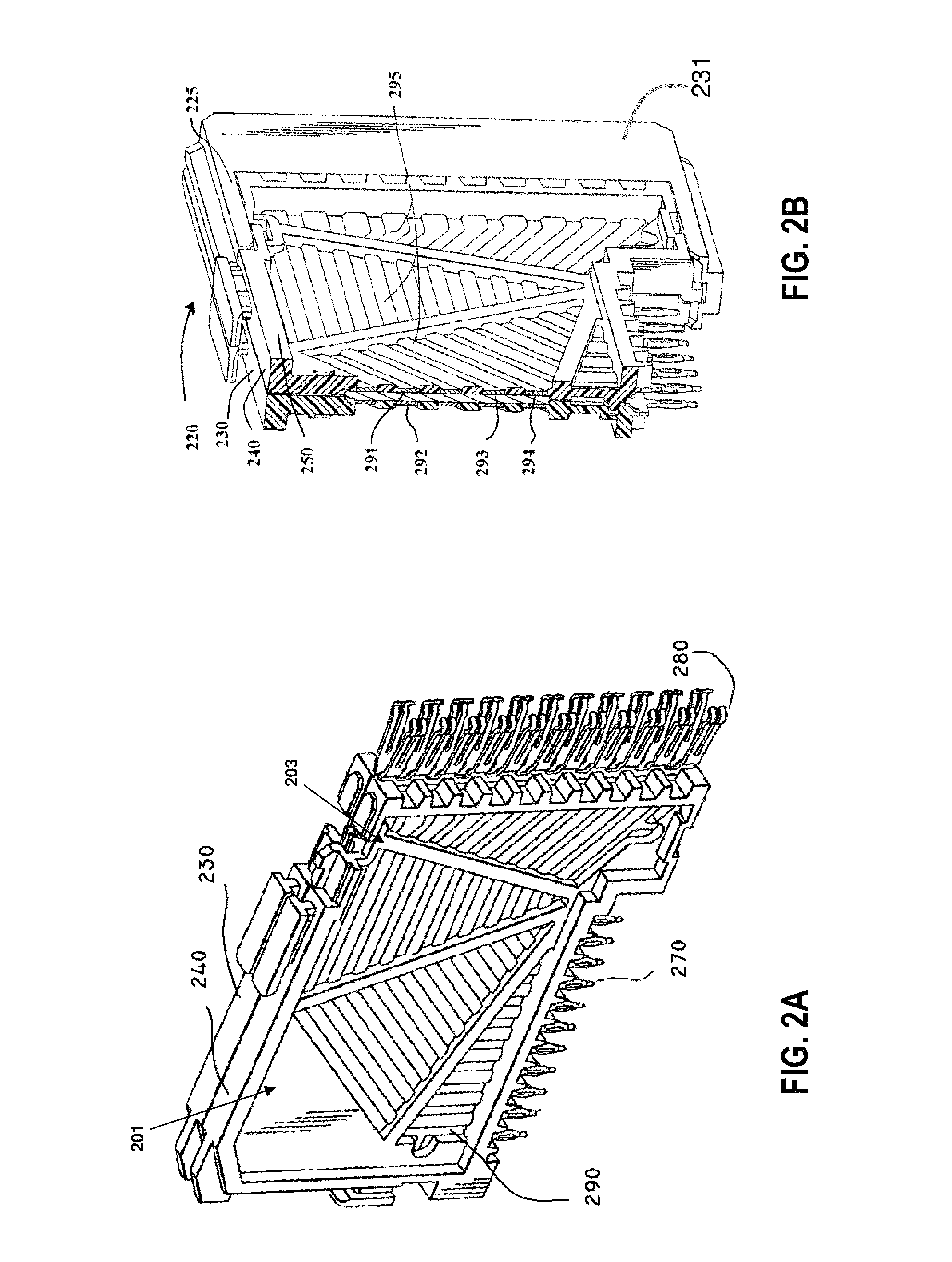
[0039]The inventor has recognized and appreciated that an improved high speed, high density interconnection system may be achieved using a hybrid shield. A hybrid shield may incorporate lossy portions and conductive portions. Without being bound by any particular theory of operation, the inventor believes that the selective incorporation of metal into the hybrid shield improves the effectiveness of the lossy material at dissipating electromagnetic energy that might otherwise contribute to cross talk, even if the metal portions are floating. As a result, the hybrid shield may be made relatively thin such that it can be incorporated into an electrical connector, or other portion of the interconnection system, in which cross talk can arise. Yet, the amount of conductive material present may be small enough that it does not cause resonances or significantly alter the impedance of conductive elements acting as signal conductors at frequencies in the desired range of operating frequencies...


PUM

PropertyMeasurementUnit
thicknessaaaaaaaaaa
thicknessaaaaaaaaaa
insertion lossaaaaaaaaaa

Abstract

An electrical connector with reduced cross talk and controlled impedance. The connector comprises hybrid shields with lossy portions and conductive portions. The synergistic effect of the lossy portions and the conductive portions allows the hybrid shields to be relatively thin such that they can be incorporated into the mating interface regions or other mechanically constrained regions of the connector to provide adequate crosstalk suppression without undesirably impacting impedance. The conductive portions may be shaped to preferentially position the conductive regions adjacent signal conductors susceptible to cross talk to further contribute to the synergy. The conductive regions may include holes to contribute to desired electrical properties for the connector.

Description

RELATED APPLICATIONS[0001]This application claims priority under 35 U.S.C. §119(e) to U.S. provisional patent application Ser. No. 61 / 548,107, filed on Oct. 17, 2011, which is hereby incorporated by reference in its entity.BACKGROUND[0002]This invention relates generally to electrical interconnection systems and more specifically to improved signal integrity in interconnection systems, particularly in high speed electrical connectors.[0003]Electrical connectors are used in many electronic systems. It is generally easier and more cost effective to manufacture a system on several printed circuit boards (“PCBs”) that are connected to one another by electrical connectors than to manufacture a system as a single assembly. A traditional arrangement for interconnecting several PCBs is to have one PCB serve as a backplane. Other PCBs, which are called daughter boards or daughter cards, are then connected through the backplane by electrical connectors.[0004]Electronic systems have generally ...

Claims


Application Information

Patent Timeline
Patent Type & Authority Patents(United States)
IPC IPC(8): H01R13/648H01R12/73H01R13/6461H01R13/6581H01R43/00
CPCH01R13/6581H01R43/00H01R13/6461H01R12/735H01R12/737H01R13/6585H01R13/6598Y10T29/49208
Inventor PANIAGUA, JOSE RICARDO
Owner AMPHENOL CORP
Why Eureka
Try Eureka