
Integrated output combiner for amplifier system

a technology of amplifier system and output combiner, which is applied in the direction of amplifiers, amplifiers with semiconductor devices/discharge tubes, amplifiers, etc., can solve the problems and achieve the effect of increasing the size, weight, and cost of the overall prior system

Active Publication Date: 2015-04-14
SKYWORKS SOLUTIONS INC
View PDF8 Cites 13 Cited by
  • Summary
  • Abstract
  • Description
  • Claims
  • Application Information

AI Technical Summary

Benefits of technology

This patent is about a new output combiner circuit for electronic amplifiers. It is composed of three parts: a first circuit, a second circuit, and a power sampling coupler. These three parts are all integrated into a single circuit, which makes it smaller, lighter, and less expensive than previous systems. The integrated circuit can be a multi-layered one. This invention simplifies the process of combining the output of multiple amplifiers, making it more efficient and cost-effective.

Problems solved by technology

Thus in the present invention all components of the output combiner are provided in a single integrated circuit, in contrast to the prior art in which the components are separate, resulting in increased size, weight, and cost of the overall prior system.

Method used


Image

  • Integrated output combiner for amplifier system
  • Integrated output combiner for amplifier system
  • Integrated output combiner for amplifier system

Examples


Embodiment Construction

[0021]The invention can be best understood with reference to the detailed figures and description set forth herein. Various embodiments are discussed below with reference to the figures. However, those skilled in the art will readily appreciate that the detailed description given herein with respect to these figures is just for explanatory purposes. The disclosed systems extend beyond the described embodiments. For example, those skilled in the art will appreciate that in light of the teachings presented, multiple alternate and suitable approaches may be realized, to implement the functionality of any detail described herein, beyond the particular implementation choices in the following embodiments described and shown.

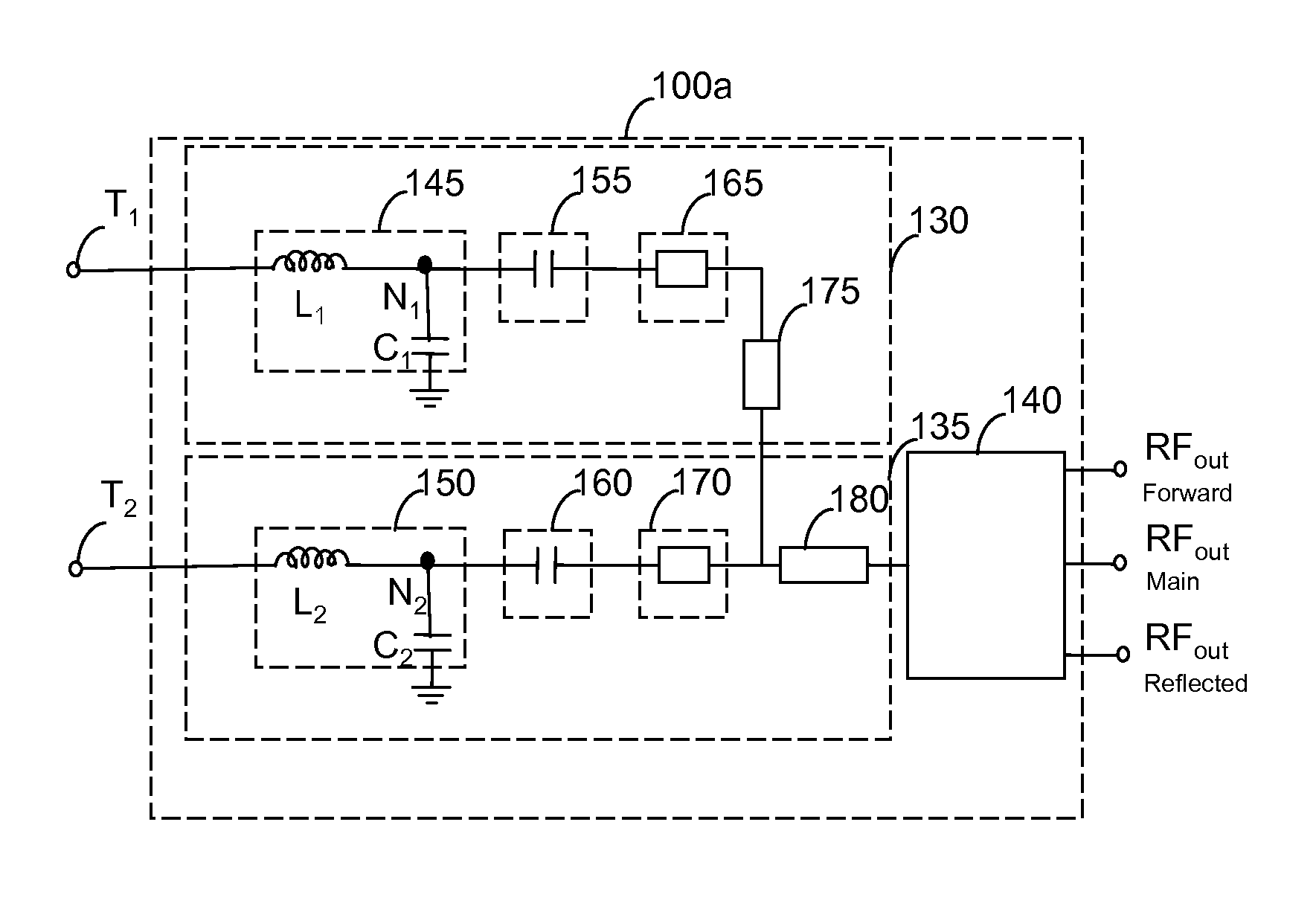
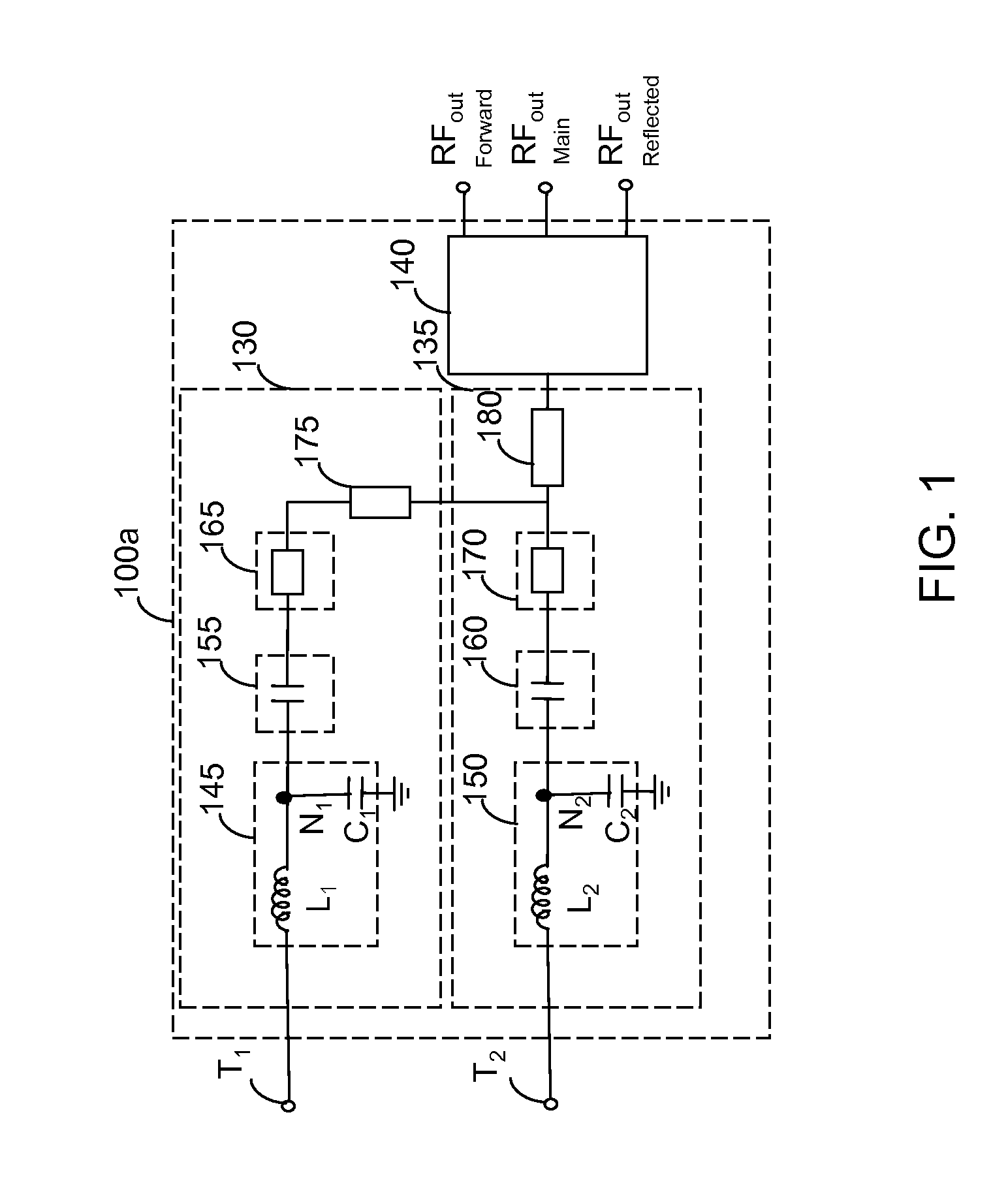
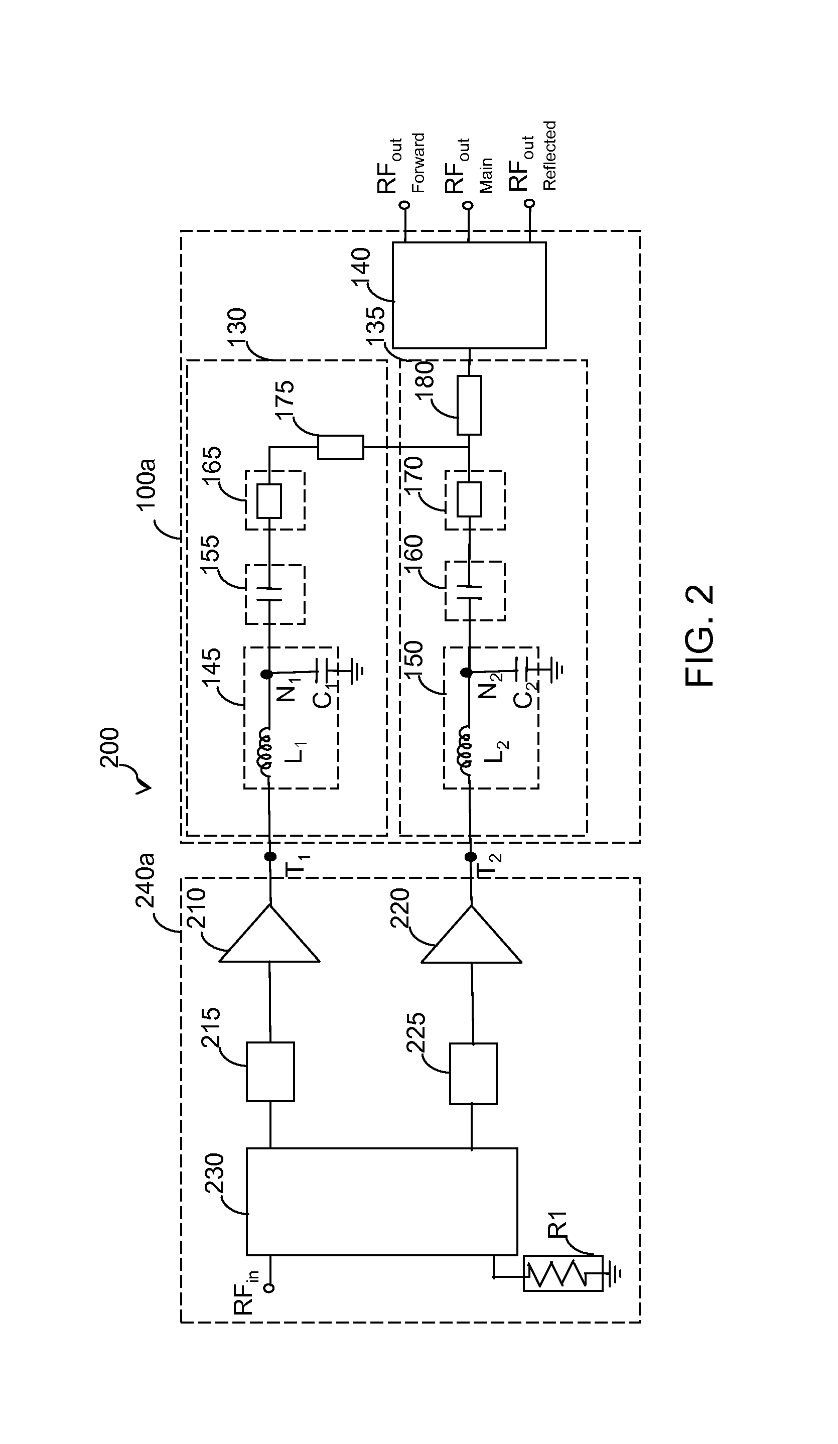
[0022]FIG. 1 illustrates an integrated circuit 100a (i.e., output combiner) in accordance with an embodiment of the invention. The integrated circuit 100a corresponds to an output combiner circuit for an amplifier system. The integrated circuit 100a includes a first ci...


PUM


Abstract

An output matching circuit for electronic amplifiers in the form of an integrated circuit is disclosed. The integrated circuit includes a first circuit, a second circuit, and a power sampling coupler. The first circuit is coupled to output of a first amplifier. The first circuit comprises a first matching section and an impedance inverter. The second circuit is coupled to output of a second amplifier, wherein the second circuit comprises a second matching section. The power sampling coupler is coupled to the first circuit and the second circuit, wherein the first circuit, the second circuit, and the power sampling coupler are fabricated as a single integrated circuit.

Description

CROSS REFERENCE TO RELATED APPLICATION[0001]This application claims priority from the U.S. provisional application No. 61 / 514,380 titled: “Improved Doherty Amplifier” filed on Aug. 2, 2011, the disclosure of which is hereby incorporated by reference.TECHNICAL FIELD[0002]The present invention generally relates to power amplifiers. More specifically, the present invention relates to an output matching network for the power amplifiers used in the field of communication devices.BACKGROUND OF THE INVENTION[0003]In recent times, various wireless communication systems use an amplifier system such as Doherty RF power amplifier in the base stations and mobile devices such as mobile phones due to their power efficiency. In many applications, it is highly desirable to reduce the cost, size and weight of the amplifier used in these communication systems. Doherty RF power amplifiers are increasingly being used due to their high-performance, reliability, and cost effectiveness. Doherty RF power a...

Claims


Application Information

Patent Timeline
Patent Type & Authority Patents(United States)
IPC IPC(8): H03H7/38H03H9/17
CPCH03H9/17H03H7/0115H03H7/38H03H2001/0085H03H7/461H03F1/0288H03F1/565H03F3/195H03F3/24H03F2200/222H03F2200/387
Inventor OZARD, KENNETH SEAN
Owner SKYWORKS SOLUTIONS INC
Learn More