Terminal structure of superconducting cable conductor and terminal member used therein
a technology of superconducting cable and terminal member, which is applied in the direction of superconducting magnets/coils, coupling device connections, magnetic bodies, etc., can solve the problems of mechanical damage of superconducting tape and burning out the superconducting layers, and achieve low electrical connection resistance and high mechanical strength.
- Summary
- Abstract
- Description
- Claims
- Application Information
AI Technical Summary
Benefits of technology
Problems solved by technology
Method used
Image
Examples
first embodiment
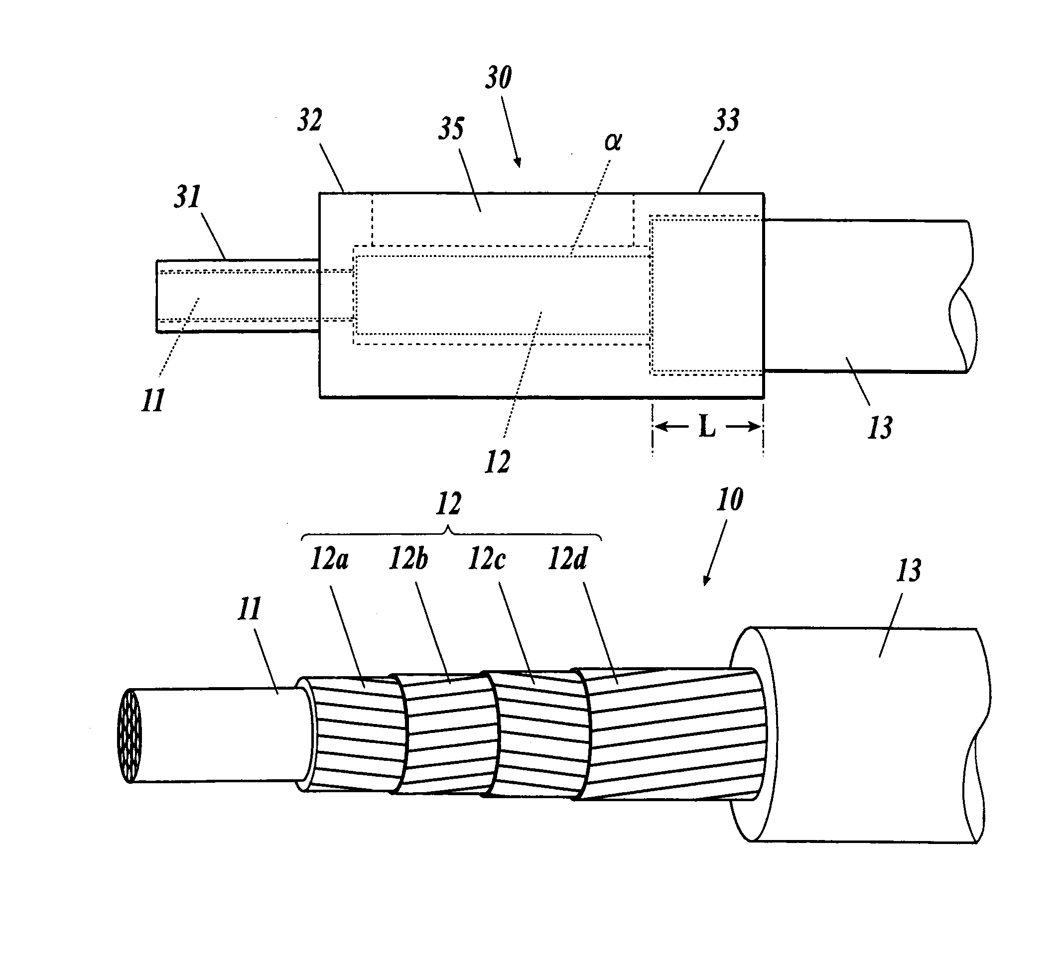
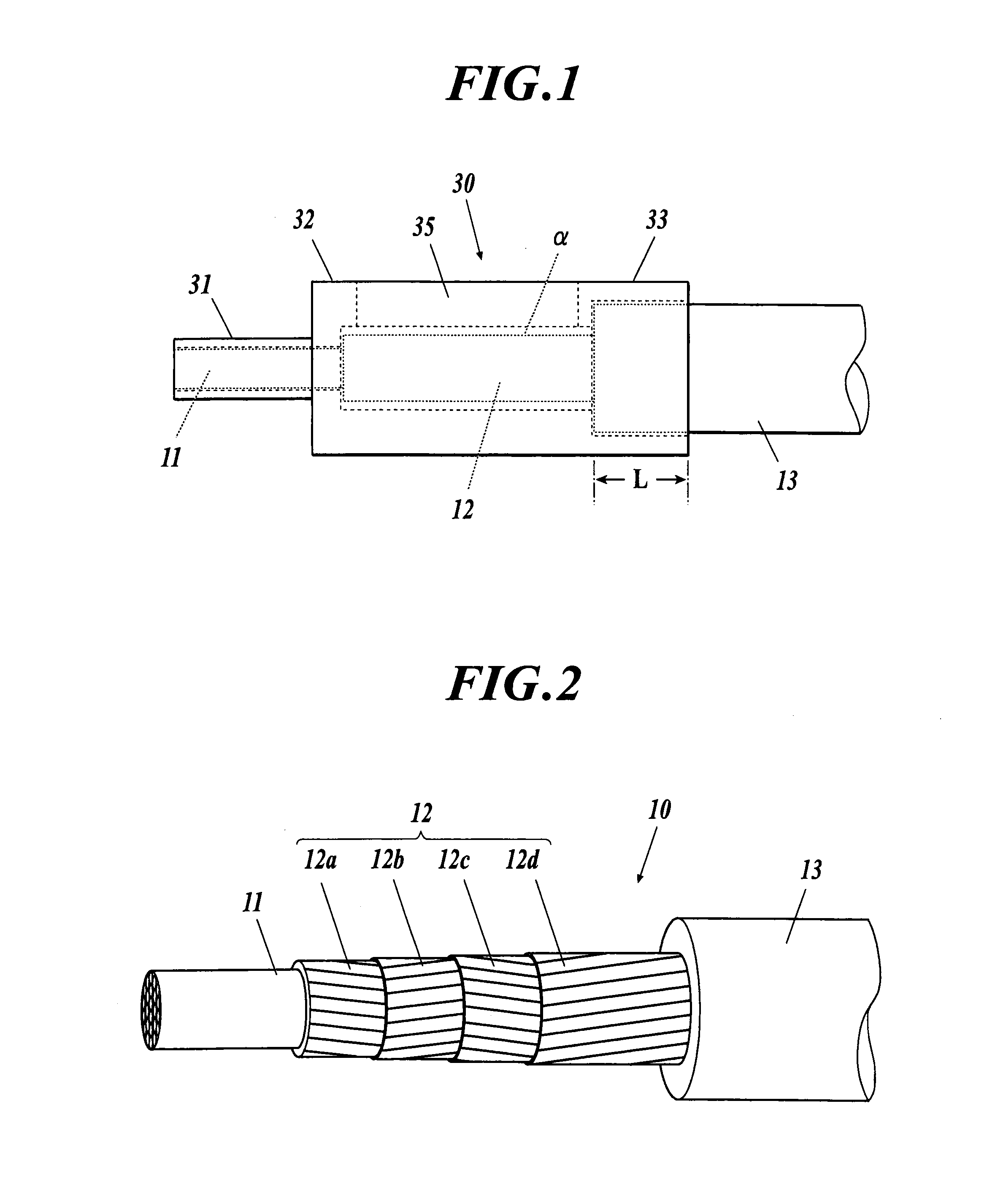
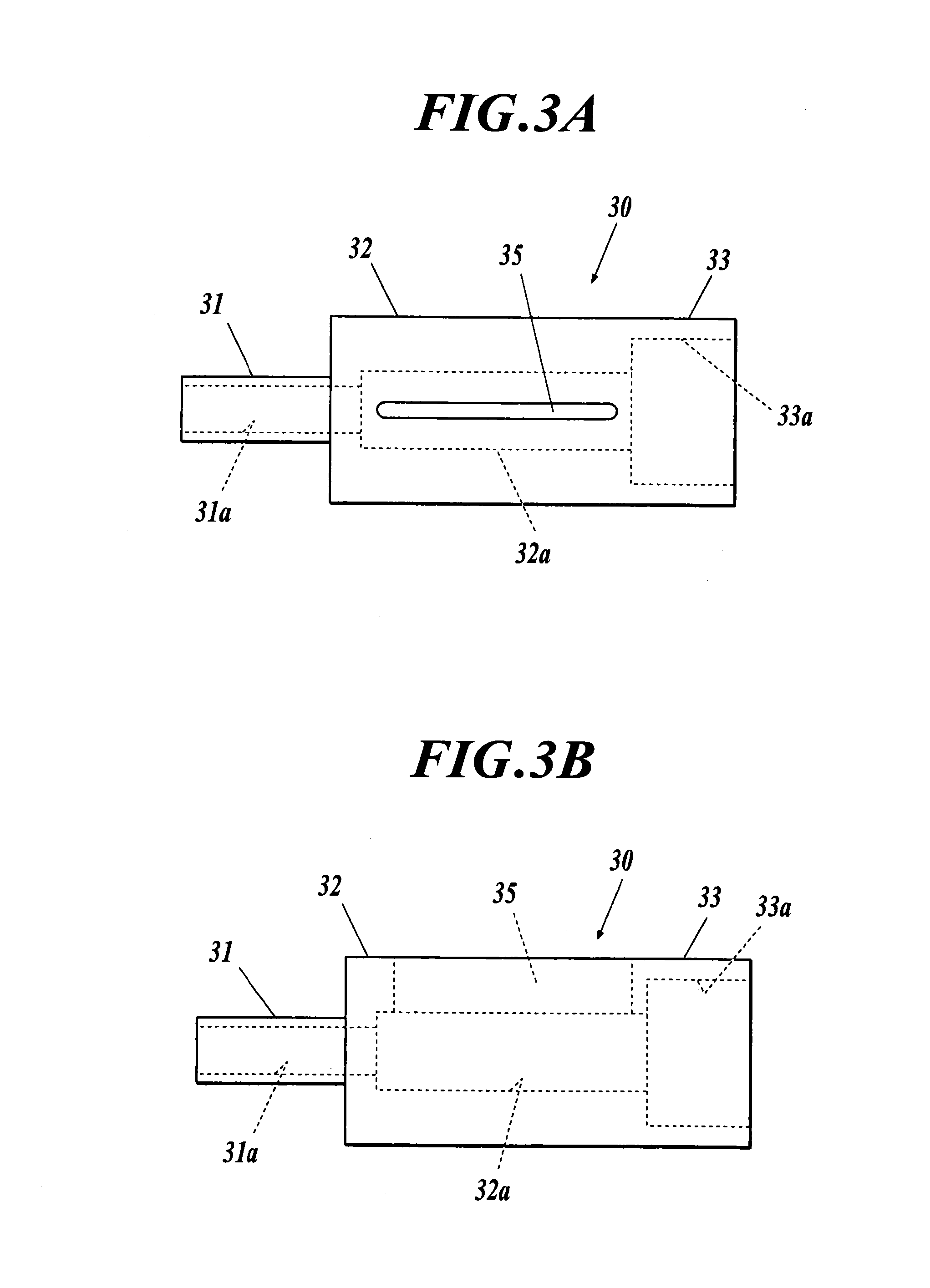
[0046]In the first embodiment, superconducting tapes are helically wound without gap around a central support 11 to form superconducting layers 12, and an insulating paper is wound over the outer surface of the superconducting layers 12 to form an insulating layer 13. Here, the central support 11 may be a conductor composed of a stranded wire of multiple Cu wires or Al wires. Alternatively, the central support 11 may be a hollow conductor composed of a spiral or flexible core tube with Cu or Al wires wound therearound. The superconducting tapes wound around the central support 11 may be a Bi-based or Y-based superconducting tape. In the present embodiment, Y-based superconducting tapes of 4 mm in width and 0.2 mm in thickness are wound to form the superconducting layers 12.
[0047]The insulating layer 13 is a wound tape of insulating paper or semi-synthetic paper of 20 mm in width and 0.1 mm in thickness. The thickness of the insulating layer 13 is about 6 mm for a 66-kV class superco...
second embodiment
[0059]FIGS. 5A to 5D show a second embodiment of the present invention. A metal sleeve 30 includes a first cylindrical portion 31, a second cylindrical portion 32 and a third cylindrical portion 33, which are coaxially arrange and are adjacent to each other at the end of each cylindrical portion. The third cylindrical portion 33 has a plurality of longitudinal slits 36 arranged at intervals in the circumferential direction of the third cylindrical portion 33. These slits 36 extend longitudinally along the metal sleeve 30 over the entire length of the third cylindrical portion 33. This allows the third cylindrical portion 33 to have the properties of a spring which is compressive (or reduces in diameter) inwardly. Consequently, this structure makes it possible for the third cylindrical portion 33 to come into close contact with an insulating layer 13 without any adhesive or applied compression force.
[0060]More specifically, the diameter of the third cylindrical portion 33 is reduced,...
third embodiment
[0061]FIG. 6 shows a third embodiment of the present invention. A metal sleeve 30 includes a first cylindrical portion 31, a second cylindrical portion 32 and a third cylindrical portion 33, which are coaxially arranged and are adjacent to each other at the end of each cylindrical portion. The third cylindrical portion 33 includes a curving portion 33b on a part of the inner surface 33a. The curving portion 33b has such a curvature as to allow a cable to bend gently when a bending force is applied to the cable. This structure of the inner surface 33a of the third cylindrical portion 33 can protect the superconducting layers 12 from damage because the cable bends gently along the entire inner surfaces 33a and 33b even if a bending force is applied to the cable.
[0062]In the embodiments described above, the metal sleeve also serves as a terminal member. Alternatively, the metal sleeve may be integrated with a projection having a hole to electrically connect to a good conductor such as,...
PUM
 Abstract
Description
Claims
Application Information
 - R&D
- Intellectual Property
- Life Sciences
- Materials
- Tech Scout
- Unparalleled Data Quality
- Higher Quality Content
- 60% Fewer Hallucinations
Browse by: Latest US Patents, China's latest patents, Technical Efficacy Thesaurus, Application Domain, Technology Topic, Popular Technical Reports.
© 2025 PatSnap. All rights reserved.Legal|Privacy policy|Modern Slavery Act Transparency Statement|Sitemap|About US| Contact US: help@patsnap.com


