Piezoelectric acceleration sensor

a piezoelectric vibrator and acceleration sensor technology, applied in the direction of acceleration measurement using interia forces, instruments, semiconductor devices, etc., can solve the problems of insufficient output sensitivity, difficult performance testing, complicated process for polarizing the piezoelectric vibrator, etc., to achieve superior mass productivity, high output sensitivity, and reduced size

Active Publication Date: 2015-04-28
TOKIN CORP
View PDF17 Cites 4 Cited by
  • Summary
  • Abstract
  • Description
  • Claims
  • Application Information

AI Technical Summary

Benefits of technology

[0013]According to the present invention, a piezoelectric ceramics is supported by a structure different from the existing structures so that it is possible to obtain a piezoelectric acceleration sensor which has high output sensitivity while having a reduced size. Moreover, the piezoelectric acceleration sensor according to the present invention has superior mass productivity.

Problems solved by technology

However, enough output sensitivity is not gotten by any means suggested hitherto.
Moreover, when the supporting structure disclosed in Patent Document 1 or Patent Document 2 is adopted, it is impossible to do performance test until the piezoelectric ceramics is installed in the storage case (i.e. until production of the piezoelectric acceleration sensor is almost done).
When the technology of Patent Document 3 is adopted, complicated processes are required to polarize the piezoelectric vibrator.

Method used


Image

  • Piezoelectric acceleration sensor
  • Piezoelectric acceleration sensor
  • Piezoelectric acceleration sensor

Examples


first embodiment

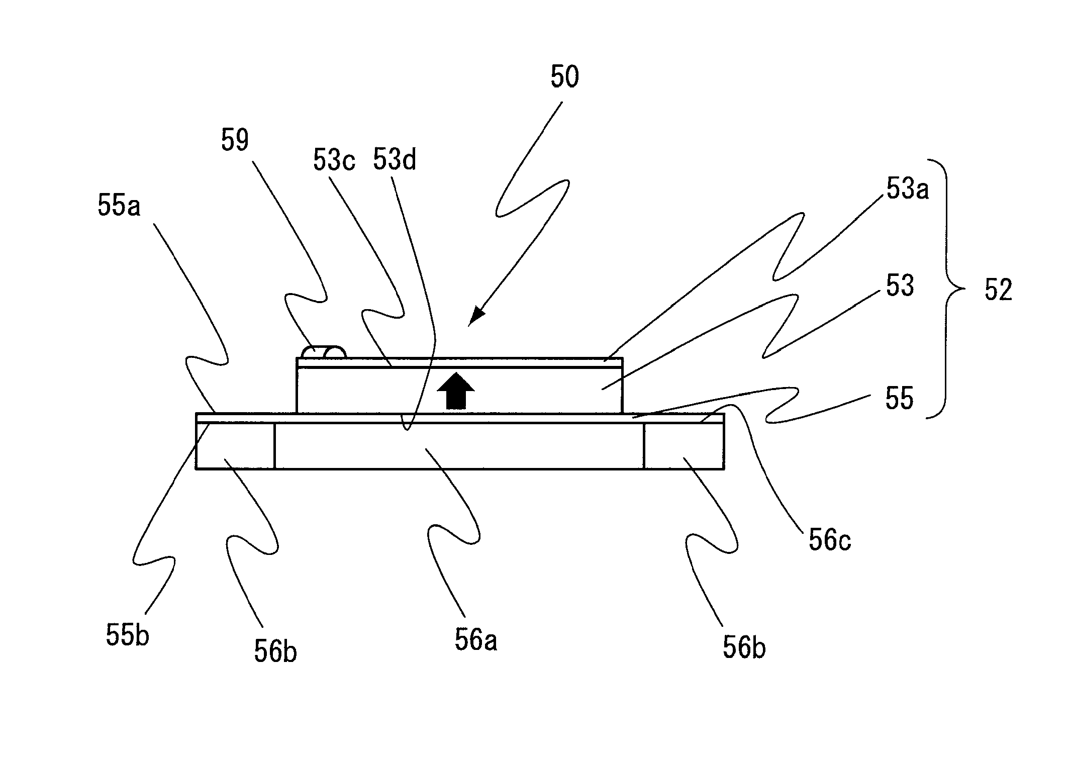
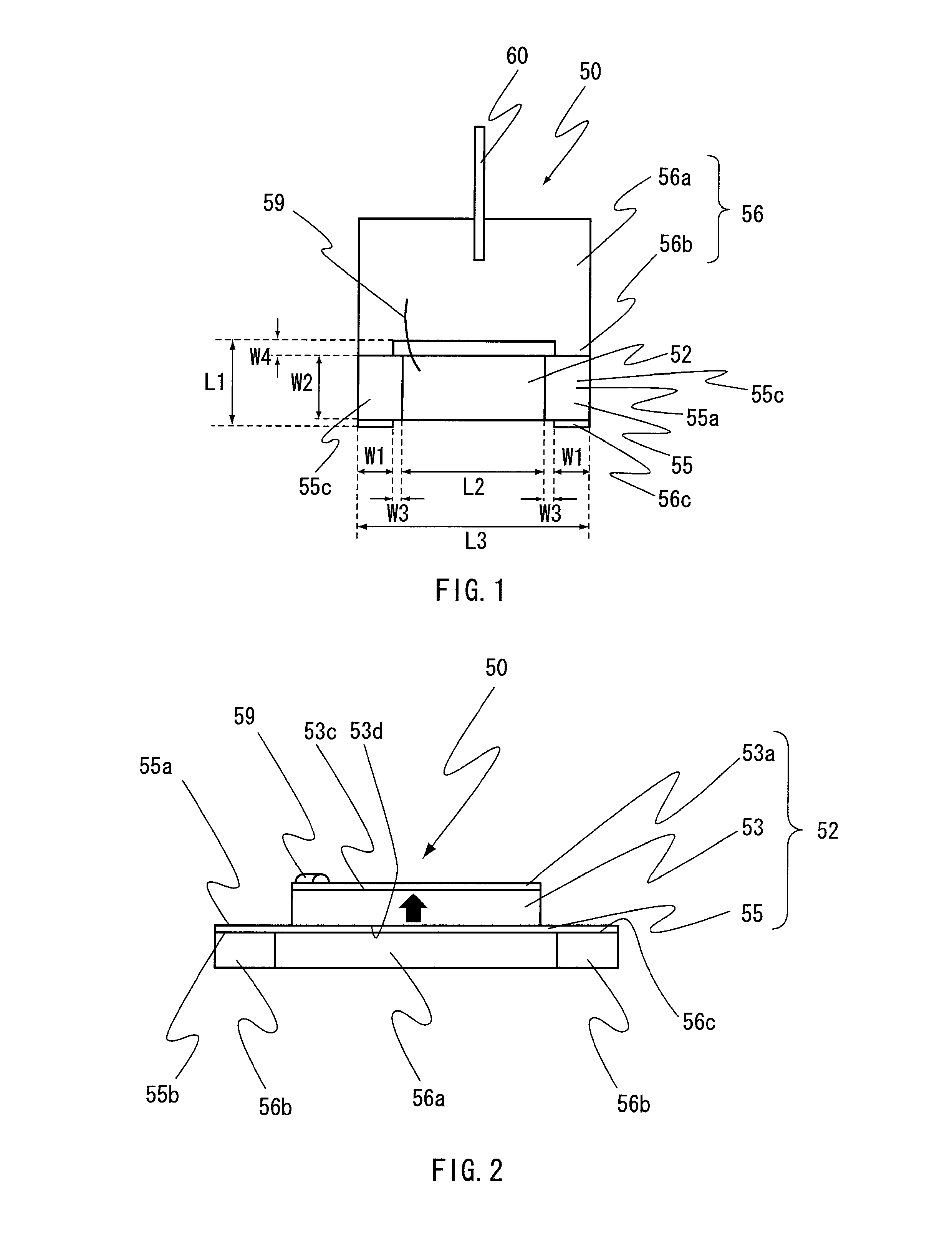
[0025]As shown in FIGS. 1 and 2, a piezoelectric acceleration sensor 50 according to a first embodiment of the present invention comprises a circuit board 56, a lead 59, an output cable 60, a piezoelectric ceramic plate (piezoelectric element) 53 and a metallic sheet 55.

[0026]The circuit board 56 includes a circuit portion 56a and base portions 56b. The circuit portion 56a is formed in a rectangular flat shape. The base portion 56b is formed in a rectangular flat shape. The base portion 56b protrudes from an end portion of the circuit portion 56a. According to the present embodiment, the two base portions 56b project in parallel to each other in a common plane from in the vicinity of opposite end portions of one side of the circuit portion 56a, respectively. In other words, the circuit board 56 is formed in a U-like shape by cutting a middle part of one side of a rectangular circuit board. The circuit portion 56a has an amplifier circuit or the like installed thereon. The lead 59 an...

second embodiment

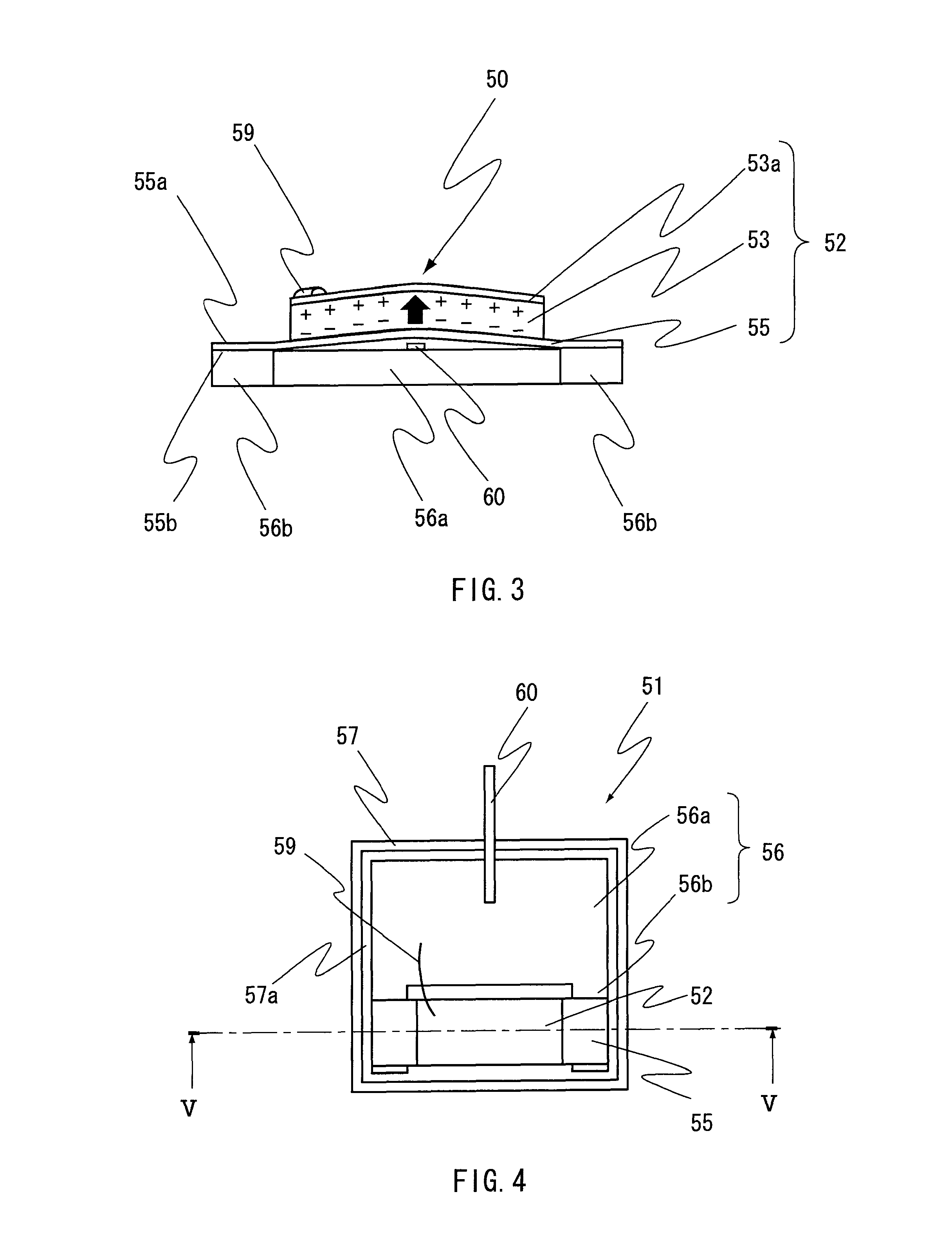
[0041]As shown in FIGS. 4 and 5, a piezoelectric acceleration sensor 51 according to a second embodiment of the present invention is configured so that the piezoelectric acceleration sensor 50 according to the first embodiment is accommodated within a case 57.

[0042]The case 57 is made of a material which has such stiffness that deformation due to expected acceleration does not occur. The inside of the case 57 is formed with an accommodating space 57a having a support surface 57b. The accommodating space 57a is formed in a size so as to be able to accommodate the circuit board 56 under a state where the piezoelectric vibrator 52 is fixed to and supported by the circuit board 56. The circuit portion 56a and the base portion 56b of the circuit board 56 are adhered to the support surface 57b by a thermosetting epoxy resin or the like so that the support surface 57b is perpendicular to the polarized direction. In other words, a lower surface 56d (opposite surface which is opposite, in th...

example 1

[0054]An example of the piezoelectric acceleration sensor 50a shown in FIG. 6 was made and accommodated within the case 57. Specifically, the piezoelectric ceramic plate 53 having the length L2 of 6.0 mm of the principal surface, the width W2 of 2.0 mm and the height of 0.3 mm was made of a PZT material. The upper electrode 53a and the lower electrode 53b, each made of a silver, were uniformly formed on a pair of the principal surfaces of the piezoelectric ceramic plate 53 so that the piezoelectric vibrator 52a was made. In addition, the circuit board 56 having thickness of 0.5 mm was made of an alumina material. The circuit board 56 is formed in a U-like shape as a whole. In detail, the base portions 56b each having a rectangular shape of 2.5 mm×0.5 mm are integrally provided at opposite ends of the circuit portion 56a having a rectangular shape of 6.0 mm×3.0 mm. A general amplifier circuit using Field Effect Transistor (FET) is installed on the circuit portion 56a. The base portio...


PUM


Abstract

A piezoelectric acceleration sensor comprises a piezoelectric element, a metallic sheet and a circuit board. The piezoelectric element is polarized in a predetermined direction. The circuit board includes a circuit portion and a roughly flat shaped base portion. The base portion protrudes from an end portion of the circuit portion. One of surfaces of the metallic sheet is fixed to and supported by a surface of the base portion. The piezoelectric element is fixed to and supported by a remaining one of the surfaces of the metallic sheet in a manner that the piezoelectric element and the base portion do not overlap each other in the predetermined direction.

Description

[0001]This application is a U.S. National Phase Application under 35 USC 371 of International Application PCT / JP2010 / 066756 filed Sep. 28, 2010.TECHNICAL FIELD[0002]This invention relates to a piezoelectric acceleration sensor which is used for a purpose such as detecting vibrations. Especially, this invention relates to a preferable support structure of a piezoelectric vibrator which is used in the piezoelectric acceleration sensor.BACKGROUND ART[0003]Recently, more and more electronic equipments become to be installed in a DVD / BD recorder, a television, a portable equipment or the like. Moreover, the precision of the installed electronic equipment is improved. Demands on reliability of the electronic equipment are continuously increasing. It is required a low-price and reduced-size acceleration sensor having high output sensitivity of 100 mV / G or more in order to detect impact applied to the electronic equipment or vibration which the electronic equipment itself generates.[0004]As...

Claims


Application Information

Patent Timeline
Patent Type & Authority Patents(United States)
IPC IPC(8): G01P15/09G01P1/02H01L41/09H01L41/113
CPCG01P15/09H01L41/0933H01L41/1132H01L41/1136H01L29/84H10N30/20H10N30/302H10N30/306H10N30/2041
Inventor SAITO, MASUTO
Owner TOKIN CORP
Why Eureka
Try Eureka