Nuclear fusion reactor first wall component and production process thereof

a technology of nuclear fusion reactor and first wall, applied in the direction of electrical equipment, climate sustainability, electrical components, etc., can solve the problems of residual fabrication degrade the quality of diffused welded assemblies, and insufficient mechanical behaviour, so as to reduce mechanical stress at the interface, the effect of improving thermal fatigue behaviour

Inactive Publication Date: 2015-04-28
COMMISSARIAT A LENERGIE ATOMIQUE ET AUX ENERGIES ALTERNATIVES
View PDF10 Cites 0 Cited by
  • Summary
  • Abstract
  • Description
  • Claims
  • Application Information

AI Technical Summary

Benefits of technology

[0029]The object of the invention is to propose and to produce a first wall component suitable for a nuclear fusion reactor, in particular presenting an improved thermal fatigue behaviour compared with a reference junction, while at the same time avoiding the presence of intermetallic compounds and limiting the mechanical stresses of the structure.

Problems solved by technology

The junction between the beryllium and the copper alloy (Be / Cu alloy) can in fact present an insufficient mechanical behaviour in the field of application of first wall components for a nuclear fusion reactor for several reasons:beryllium and copper react with one another above 400° C. to form intermetallic compounds.
These intermetallic compounds weaken the junction between the beryllium and the copper alloy and can lead to breaking of the latter when final machining is performed or in premature manner during testing designed to test its mechanical behaviour.beryllium has a very thermally stable oxide layer at its surface which can slow down diffusion at the beryllium-copper alloy interface and therefore degrade the quality of the diffused welded assembly.beryllium and copper alloy are materials that have different thermal expansion coefficients and Young's modulus, which gives rise to the occurrence of residual fabrication stresses at the interface.
Formation of these oxides at the surface of the barrier layers may however limit the diffusion process thereby reducing the mechanical strength of the Be / diffusion barrier / copper alloy assembly.
However, the results of these tests are difficult to use and to compare with one another as, very often, the test models have dimensions and cooling conditions that are not very well known and / or are different.
The cooling conditions of a junction subjected to a high-intensity transient heat flux do however greatly influence its thermal fatigue behaviour.
It is consequently difficult to appreciate the improvements provided by the assemblies made in the literature compared with a Be / Cu alloy reference junction, with or without a compliant layer for uses as first wall component of a fusion reactor.

Method used


Image

  • Nuclear fusion reactor first wall component and production process thereof
  • Nuclear fusion reactor first wall component and production process thereof
  • Nuclear fusion reactor first wall component and production process thereof

Examples


first embodiment

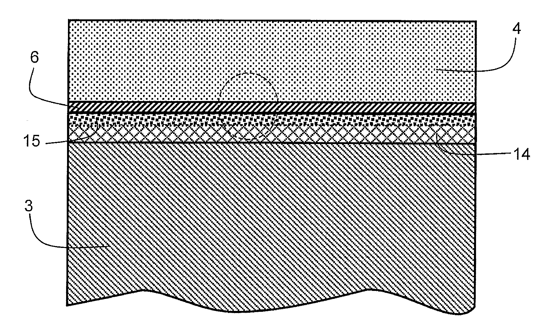
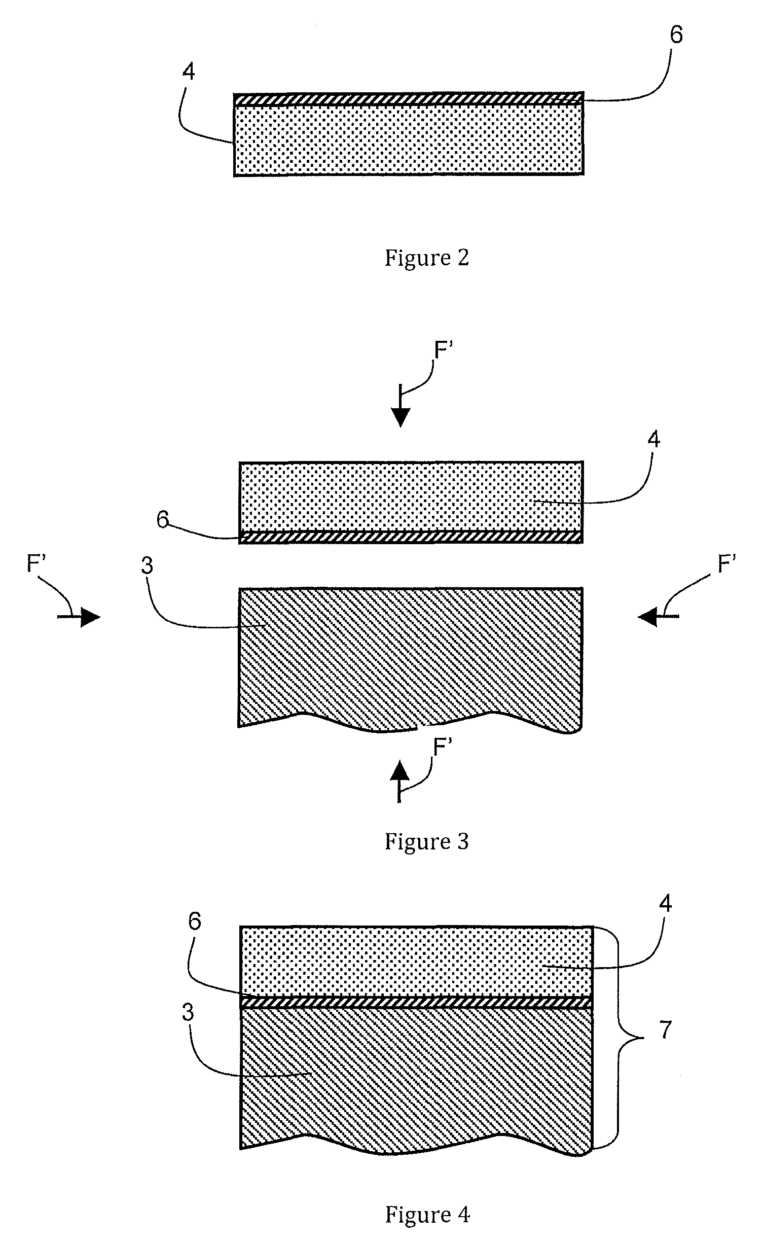
[0042]FIGS. 2 to 4 illustrate a first wall component for a nuclear fusion reactor.

[0043]In FIG. 2, intermediate niobium layer 6 is formed directly on a free surface of beryllium element 4 in order to be directly in contact with beryllium element 4. Intermediate niobium layer 6 advantageously presents a thickness comprised between 1 μm and 20 μm and advantageously between 1 μm and 5 μm. This formation step can be performed by any type of means, such as physical vapor deposition (PVD), vacuum evaporation, plasma projection or electrolytic deposition. However, it is preferably performed by PVD. Furthermore, the free surface of beryllium element 4 designed to receive intermediate niobium layer 6 is if necessary cleaned before formation of intermediate niobium layer 6. This can be obtained by a conventional degreasing and de-oxidation operation such as chemical etching, but also by cleaning techniques associated with deposition methods, such as ion bombardment for PVD.

[0044]Then, as illu...

second embodiment

[0055]FIGS. 5 to 7 illustrate a first wall component for a nuclear fusion reactor using a mechanical stress-reducing layer 8.

[0056]In FIG. 5, intermediate niobium layer 6 is formed directly on a free surface of beryllium element 4 in order to be directly in contact with beryllium element 4. Intermediate niobium layer 6 advantageously presents a thickness comprised between 1 μm and 20 μm and advantageously between 1 μm and 5 μm. As in the previous embodiment, this formation step can be performed by any type of means. However it is preferably performed by PVD. Furthermore, the free surface of beryllium element 4 designed to receive intermediate niobium layer 6 is if necessary cleaned before formation of intermediate niobium layer 6.

[0057]Then, as illustrated in FIG. 6, a mechanical stress-reducing layer 8 (also called compliant layer), for example made from pure copper such as an oxygen-free high-conductivity copper, known under the abbreviation CuC1 or Cu—OF (Oxygen-free high-conduct...


PUM

PropertyMeasurementUnit
thicknessaaaaaaaaaa
thicknessaaaaaaaaaa
thicknessaaaaaaaaaa

Abstract

A nuclear fusion reactor first wall component includes a copper alloy element, an intermediate metal layer made from niobium and a beryllium element, directly in contact with the intermediate metal layer. The intermediate niobium layer is further advantageously associated with a mechanical stress-reducing layer formed by a metal chosen from copper and nickel. This mechanical stress-reducing layer is in particular arranged between the intermediate niobium layer and the copper alloy element. Furthermore, when the mechanical stress-reducing layer is made from pure copper, a layer of pure nickel can be inserted between the niobium and the pure copper before diffusion welding. Such a component presents the advantage of having an improved thermal fatigue behavior while at the same time preventing the formation of intermetallic compounds at the junction between the beryllium and the copper alloy.

Description

BACKGROUND OF THE INVENTION[0001]The invention relates to a nuclear fusion reactor first wall component provided with a stack successively comprising:[0002]an element made from copper alloy,[0003]an intermediate metal layer and[0004]a beryllium element, directly in contact with the intermediate metal layer.[0005]The invention also relates to a method for manufacturing one such component.STATE OF THE ART[0006]For nuclear fusion reactors and in particular for the future thermonuclear fusion reactor ITER (International Thermonuclear Experimental Reactor), the vacuum chamber of the reactor is covered by first wall components which are directly facing the plasma. Their role is to protect the personnel working on the site and the nuclear installations surrounding the vacuum chamber of the reactor from the thermal radiation and neutron flux.[0007]FIG. 1 illustrates a schematic diagram of a first wall component 1. It is constituted by an assembly of three different elements:[0008]an element...

Claims


Application Information

Patent Timeline
Patent Type & Authority Patents(United States)
IPC IPC(8): G21C11/02B23K20/02B23K20/16B23K20/233B23K35/00B23K35/02B23K35/32G21B1/13
CPCG21C11/028B23K20/2333B23K35/004B23K35/007B23K35/0238G21B1/13B23K35/32B23K20/021B23K20/16Y02E30/128Y02E30/10Y02E30/30Y10T428/12458Y10T428/12493Y10T428/12903Y10T428/1291
Inventor FRAYSSINES, PIERRE-ERICBUCCI, PHILIPPELEIBOLD, JEAN-MARCRIGAL, EMMANUEL
Owner COMMISSARIAT A LENERGIE ATOMIQUE ET AUX ENERGIES ALTERNATIVES
Why Eureka
Try Eureka