Method for holding part blank by fluid expansion in additive manufactured holding portion

A manufacturing method, additive manufacturing technology, applied in the direction of processing and manufacturing, manufacturing tools, additive manufacturing, etc., can solve problems such as mechanical stress troubles, low mechanical strength, etc.

Pending Publication Date: 2022-07-08
SAFRAN AIRCRAFT ENGINES SAS
View PDF6 Cites 0 Cited by
  • Summary
  • Abstract
  • Description
  • Claims
  • Application Information

AI Technical Summary

Problems solved by technology

Such mechanical stresses can prove to be particularly troublesome when the component blank has a relatively low mechanical strength, for example when the component is a blade or more generally it comprises at least one thin wall

Method used


Image

  • Method for holding part blank by fluid expansion in additive manufactured holding portion
  • Method for holding part blank by fluid expansion in additive manufactured holding portion
  • Method for holding part blank by fluid expansion in additive manufactured holding portion

Examples


Embodiment Construction

[0037] Identical, similar or equivalent parts in different figures have the same reference numerals to facilitate transition from one figure to another.

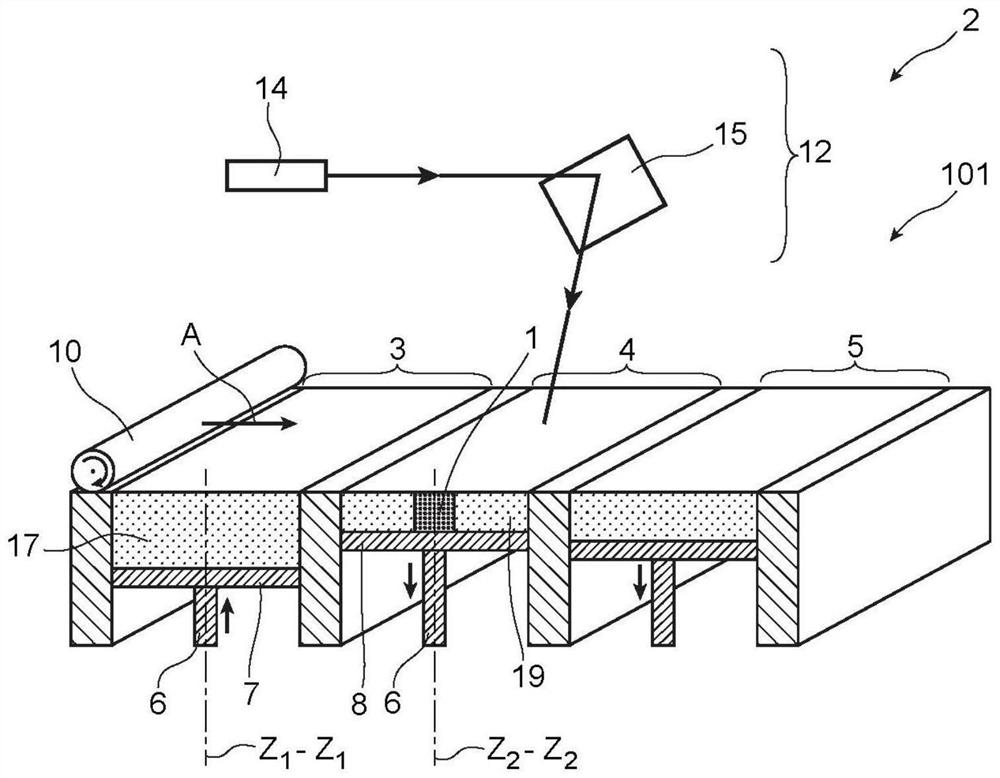
[0038] figure 1 An example of a tool 2 for manufacturing a component 1 by selective melting or selective sintering of a powder bed according to the manufacturing method of the first embodiment is shown.

[0039] Component 1 is an aircraft turbine engine component such as a blade, wall or flange. It in particular comprises at least one thin wall, which makes it relatively fragile. Nonetheless, it is designed to withstand particularly significant mechanical and / or thermal stresses during turbine engine operation. By additive manufacturing, it is manufactured from powder material 17, typically metallic material powder for aerospace applications.

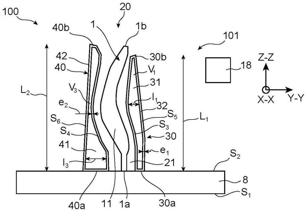
[0040] The component 1 comprises a lower end 1a, an upper end 1b opposite the lower end 1a, and a body 11 between the lower end 1a and the upper end 1b. For example, it is not com...


PUM


Abstract

The invention relates to a method for holding a component blank (1) in a holding assembly (20). The retaining assembly (20) includes a first retaining portion (30). The first holding portion (30) comprises an inner cavity (31) containing a fluid. The component blank (1) and the first holding portion (30) are at least partially produced by additive manufacturing. The holding method comprises heating the holding assembly (20) and the component blank (1) to deform the first holding portion (30) by expansion of fluid in the interior cavity (31) and to reduce a gap (21) between the component blank (1) and the holding assembly (20) by expansion of the first holding portion.

Description

technical field [0001] The present invention relates to the technical field of additive manufacturing of powder beds, also known as 3D printing. The invention more particularly relates to a method for holding a part blank, at least partially additively manufacturing a part blank and a holding assembly by layer-by-layer powder deposition, by selective melting or selective melting using a laser beam or an electron beam Sintering partially solidifies them. Background technique [0002] The selective melting or selective sintering method of the powder bed allows easy production of metal or ceramic components, such as turbine engine components that are subjected to significant mechanical and / or thermal stress. [0003] Such methods are particularly known under the abbreviations SLM ("Selective Laser Melting"), SLS ("Selective Laser Sintering"), DMLS ("Direct Metal Laser Sintering") and EBM ("Electron Beam Melting"). [0004] These methods generally include the steps of depositi...

Claims


Application Information

Patent Timeline
Patent Type & Authority Applications(China)
IPC IPC(8): B22F5/00
CPCB29C64/153B29C64/40B33Y40/20F01D25/285F05D2230/31F05D2230/22B22F5/04F05D2230/234F05D2230/40F01D5/286B22F5/009B23P6/007B22F5/007B33Y80/00B22F10/28B22F10/64Y02P10/25B33Y10/00
Inventor 吉扬·凯文·库姆斯塞巴斯蒂安·文森特·弗朗索瓦·德雷亚诺皮埃尔·让-巴蒂斯特·梅奇
Owner SAFRAN AIRCRAFT ENGINES SAS
Why Eureka
Try Eureka