Wireless charging device

a charging device and wireless technology, applied in the direction of battery overheating protection, safety/protection circuit, tobacco, etc., can solve the problems of increasing the cost, affecting the efficiency of receiving, and affecting the low cost and small size of products, so as to achieve low cost and small area, reduce the effect of heat sinks and low cos

Inactive Publication Date: 2015-04-28
KIMREE HI TECH
View PDF13 Cites 43 Cited by
  • Summary
  • Abstract
  • Description
  • Claims
  • Application Information

AI Technical Summary

Benefits of technology

[0003]The present invention aims to solve the foregoing problems, and provide a wireless charging device. Heat generation of the electronic switch of the wireless charging device is reduced, and the heat sink is greatly reduced in area or even removed.
[0004]According to an aspect of the present invention, a wireless charging device is provided. The wireless charging device comprises an electronic switch and a transmitting coil electrically connected with a power source in sequence. A control end of the electronic switch is connected with a transmitting control unit. The wireless charging device further comprises a current limiting resistance connected in serial with the transmitting coil. Compared to the traditional solution, the additional current limiting resistance limits and reduces the current passing through the electronic switch, thus effectively decreasing the heat generation on the electronic switch. In that way, the burning out of the electronic switch can be prevented. Further, because the current limiting resistance has a rather small resistance value of about 1-5 ohm (a static resistance has a small resistance of about 0.01-0.5 ohm), it can even be ignored compared with a dynamic resistance which has a resistance value as large as 20-100 ohm. Therefore, problems like power losses, low transmitting efficiencies, and low receiving efficiencies exist in the prior art can be avoided. In addition, high heat generation on resistances by traditional solution can also be prevented.
[0005]In an embodiment of the present invention, the wireless charging device further comprises a compensation capacitor connected in parallel with the transmitting coil. Thus due to the control of the PWM, a transmitting process can either be performed when the electronic switch is on, or be achieved while the switch is off (improving the transmitting efficiency), since the transmitting coil and the compensation capacitor form a circuit. While the electronic switch is off, it does not generate heat because there is no current passes through. Therefore, when the transmitting power is identified (by reducing the duty cycle of the switching tube), current passing through the electronic switch is significantly reduced and the heat generation on the electronic switch is also decreased, so as to improve the stability of the circuit.
[0008]Said wireless charging device is used to charge an electronic cigarette, further comprising an inserting hole or a sleeve coupled with the electronic cigarette. An insert total electromagnetic coupling structure is therefore formed, which has greatly improved the receiving efficiency and efficiently reduced the current passing through the electronic switch.
[0013]According to the present invention, a current limiting resistance and a compensation capacitor are applied based on traditional transmitting circuit. An insert total electromagnetic coupling structure and an insert detection are applied, which is particularly suitable for electronic cigarette. Compared to those in the prior art, the wireless charging device according to the present invention provides the following benefits: 1) high efficiency; 2) stable working status; 3) low heat generation, heat sinks could be removed or greatly be reduced in area; and 4) detecting and charging automatically, energy conservative, and environmental friendly.

Problems solved by technology

Because a high heat value can be generated on the electronic switch due to a dynamic resistance, heat sinks with large area are needed to regulate the work of the electronic switch, which increases the cost and is especially adverse to product with low cost and small size.
Furthermore, the current transmitting coil doesn't transmit and the receiving efficiency is rather low when the electronic switch is off, both causing extra heat generation of the field-effect switching tube.

Method used


Image

  • Wireless charging device
  • Wireless charging device
  • Wireless charging device

Examples


Embodiment Construction

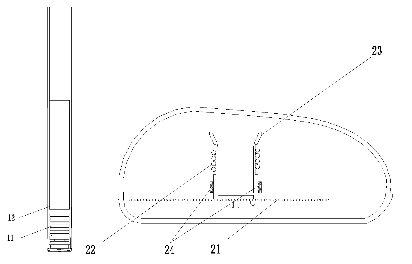
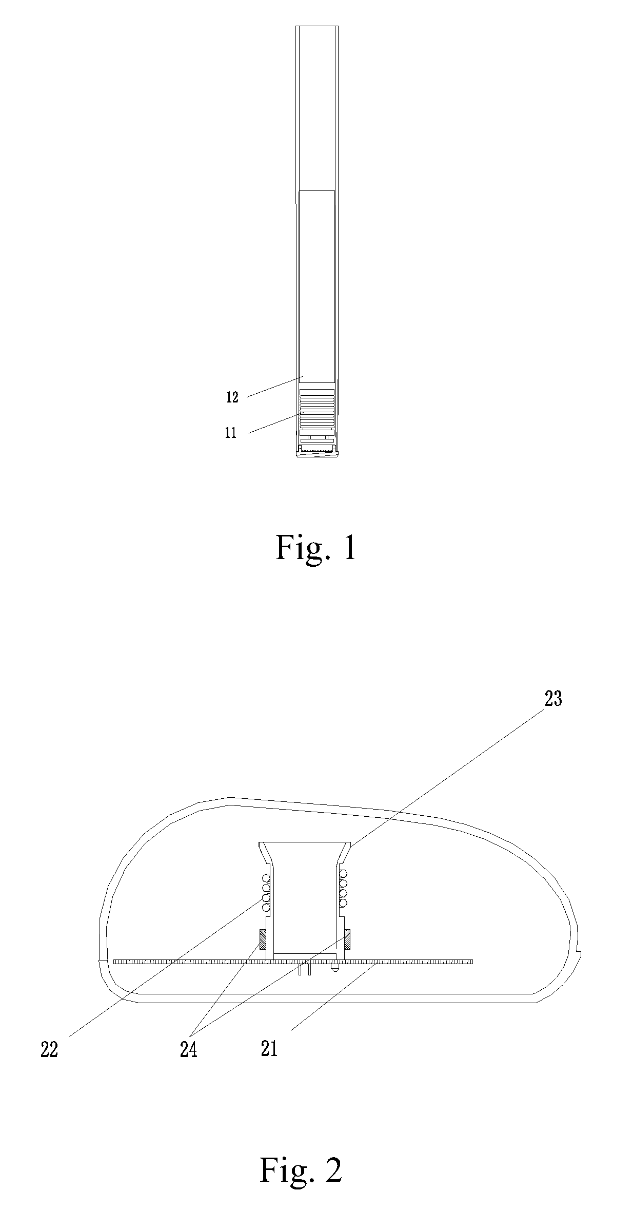
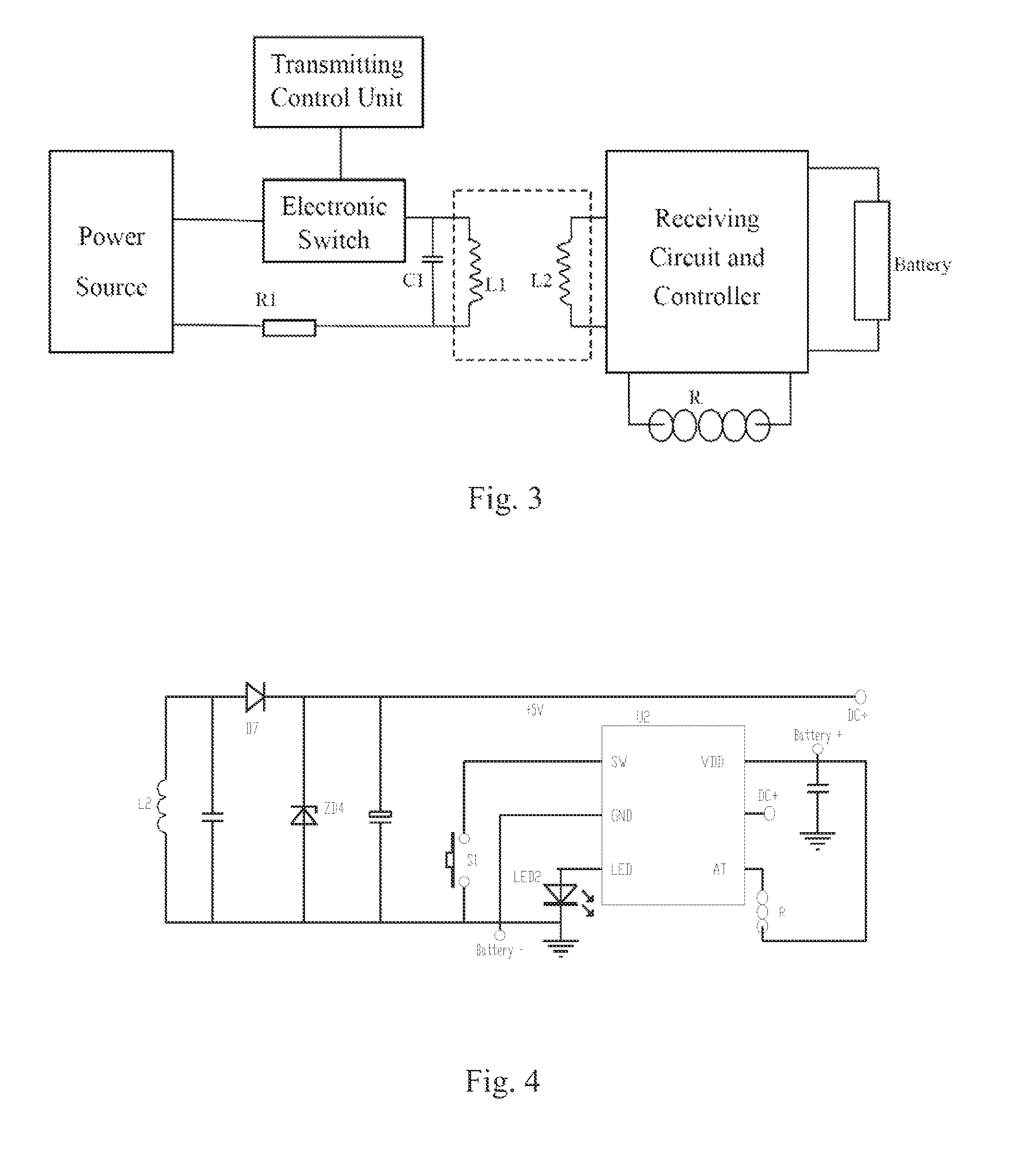
[0019]As shown in FIG. 1, an electronic cigarette according to the present invention is provided, comprising a battery 12 installed on the body of the electronic cigarette, and a receiving coil 11 provided on the head part of the electronic cigarette located in front of the battery 12. The receiving coil 11 is also labeled as L2 in FIG. 3 and FIG. 4.

[0020]As shown in FIG. 2, a wireless charging device for the electronic cigarette according to the present invention is provided, comprising a circuit board 21, a sleeve 23, a photo detector 24 for testing the insertion of the electronic cigarette, and a transmitting coil 22. The transmitting coil 22 is also labeled as L1 in FIG. 3 and FIG. 5. The transmitting coil 22 is wrapped outside the sleeve 23, corresponding to the position for inserting the receiving coil 11 of the electronic cigarette. When the electronic cigarette is installed, the receiving coil 11 is inside the transmitting coil 22 with the axes of the two coils in the same d...


PUM


Abstract

A wireless charging device comprises an electronic switch and a transmitting coil (L1) electrically connected with a power source in sequence. A control end of the electronic switch is connected with a transmitting control unit. The wireless charging device further comprises a current limiting resistance (R1) connected in serial with the transmitting coil. The wireless charging device further comprises a compensation capacitor (C1) connected in parallel with the transmitting coil. An insert total electromagnetic coupling structure is further employed for charging. Such wireless charging device is particularly suitable for electronic cigarette, with low cost, stable and reliable working status and high efficiency, and specific heat sink is not required.

Description

FIELD OF THE PRESENT INVENTION[0001]The present invention relates to wireless charging technique, more particularly to a wireless charging device with low cost and high efficiency, especially be suitable for electronic cigarette.BACKGROUND OF THE PRESENT INVENTION[0002]At present, a wireless charging device comprises a power source, an electronic switch, and a transmitting coil electrically connected in sequence. Switch on / off of the electronic switch is controlled by a Pulse Width Modulation (PWM) controller. The transmitting coil is connected to the power source through the electronic switch. A field-effect switching tube with high power usually serves as the electronic switch mentioned above. Because a high heat value can be generated on the electronic switch due to a dynamic resistance, heat sinks with large area are needed to regulate the work of the electronic switch, which increases the cost and is especially adverse to product with low cost and small size. According to a tra...

Claims


Application Information

Patent Timeline
Patent Type & Authority Patents(United States)
IPC IPC(8): H02J7/00A24F47/00A24F40/90H02J5/00H02J7/02
CPCA24F47/002A24F47/00H02J5/005H02J7/025A24F47/008H02J50/10H02J7/00304H02J7/0044A24F40/90H02J7/00309H02J50/12
Inventor XIANG, ZHIYONG
Owner KIMREE HI TECH
Why Eureka
Try Eureka