Method for designing and manufacturing custom optics

a technology of optics and manufacturing methods, applied in the direction of spectacles/goggles, instruments, prostheses, etc., can solve the problems of insufficient clinically deployed methods to determine the relative impact of these aberrations on visual performance, current contact lens designs do not provide intelligent design philosophy that allows for the minimization of these aberrations, and can not meet the needs of eye health care professionals, etc., to achieve maximum visual performance and maximize visual

Active Publication Date: 2015-05-05
UNIV HOUSTON SYST
View PDF17 Cites 2 Cited by
  • Summary
  • Abstract
  • Description
  • Claims
  • Application Information

AI Technical Summary

Benefits of technology

[0011]The present invention is directed to a method for manufacturing a customized optical lens. The method comprises a) identifying a minimal subset of optical aberrations present in an eye via image simulation, predictive metrics or a combination thereof, where correction of the optical aberrations maximizes visual performance of the eye, b) inputting physical values measured on the eye necessary to maximally stabilize an optical lens in a manner consistent with ocular health c) integrating the minimal subset of aberrations via an algorithm designed to minimize the subset of aberrations with reference to the stabilization achieved in step b) as a custom-designed surface for the optical lens effective to maximize visual performance, and d) implementing construction of the custom surface onto the stabilized lens thereby manufacturing a customized optical lens.
[0012]The present invention is directed to a related invention comprising the further method steps of evaluating the manufactured customized optical lens for optimal performance. The present invention is directed to another related invention comprising the further method steps of modifying the optical lens design and iterating steps a) and d) to improve optimization.
[0013]The present invention is also directed to an optical lens having a surface-customized correction for a minimal subset of optical aberrations maximally effecting visual performance. The customized optical lens is constructed by a method comprising a) identifying a minimal subset of optical aberrations present in an eye via image simulation, predictive metrics or a combination thereof, where correction of the optical aberrations maximizes visual performance of the eye, b) inputting physical values measured on the eye necessary to maximally stabilize the optical lens in a manner consistent with ocular health c) integrating the minimal subset of aberrations via an algorithm designed to minimize the subset of aberrations with reference to the stabilization achieved in step b) as a custom-designed surface for the optical lens effective to maximize visual performance, and d) implementing construction of the custom surface onto the stabilized lens.
[0014]The present invention is directed further to a method of correcting optical aberration to improve visual performance. The method comprises manufacturing the customized optical lens described herein using a minimal subset of optical aberrations determined for the subject and placing the customized optical lens on, in or in the path of the eye having the optical aberrations, thereby correcting the visual acuity of a subject.
[0016]The present invention is directed further still to a method for manufacturing a customized lens. The method comprises a) identifying a subset of optical aberrations b) integrating the subset of aberrations via an algorithm designed to mimic the subset of optical aberrations as a custom designed surface for the lens and c) implementing construction of the custom surface onto the lens thereby manufacturing a customized lens. The present invention also is directed to a related invention comprising the further method step of evaluating the manufactured customized lens for optimal performance.

Problems solved by technology

For example, higher order ocular aberrations can significantly impact visual performance.
While these higher order aberrations can be easily quantified, current contact lens designs do not provide an intelligent design philosophy that allows for the minimization of these aberrations and optimization of visual performance on an individual basis.
Furthermore, the current state of the art lacks sensitive clinically deployed method to determine the relative impact of these aberrations on visual performance.
Specifically, the prior art is deficient in methods to design, implement and verify custom optics using the optical and physical characteristics of the individual eye to identify significant aberrations and intelligent design of the optical zone of custom optics and fitting and stabilization properties of the lens.

Method used


Image

  • Method for designing and manufacturing custom optics
  • Method for designing and manufacturing custom optics
  • Method for designing and manufacturing custom optics

Examples


example 1

Lens Manufacture Algorithm

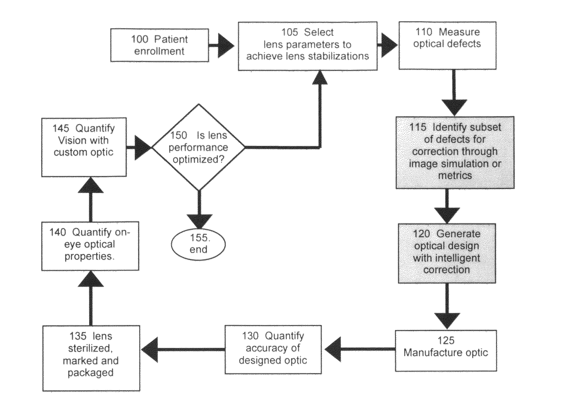
[0048]The first component of the method described herein is an algorithm by which custom optics can be designed and manufactured. This algorithm can be used to design and manufacture contact lenses for any individual for which contact lenses are clinically indicated. The algorithm is depicted in FIG. 1.

[0049]The process begins at step 100 in a manner similar to conventional lens dispensation, i.e., the subject is evaluated by a clinician. If the subject is deemed a candidate for contact lens wear, contact lens parameters such as lens base curves, diameter, prism ballast, and power are determined and are iterated until a rotationally and translationally stable lens is achieved at step 105. In order to facilitate customization of the lens to the subject's optical defects, a full description of the optical defects of the eye(s) is quantified at step 110 with the stabilized lens on and off.

[0050]At step 115 a minimal subset of the residual optical defects (lens...

example 2

Description of Optical Defects

[0052]The implementation of custom ophthalmic optics used herein is determined by wavefront sensing. Wavefront sensors can determine the optical error, also referred to as optical defects or aberrations, present in an eye. Currently, the Zernike expansion is the ANSI standard (ANSI Z80.28) fitting function for describing ocular wavefront error, and is used here to describe optical aberration. The Zernike expansion is a long-established method for defining optical errors and is not unique to the eye and is not necessary to the methods being described. Any mathematical method could be used that adequately defines the optical defects of the eye. The Zernike expansion is used herein for illustrative purposes and because it is the national standard established for describing ocular wavefront error.

example 3

Image Simulation

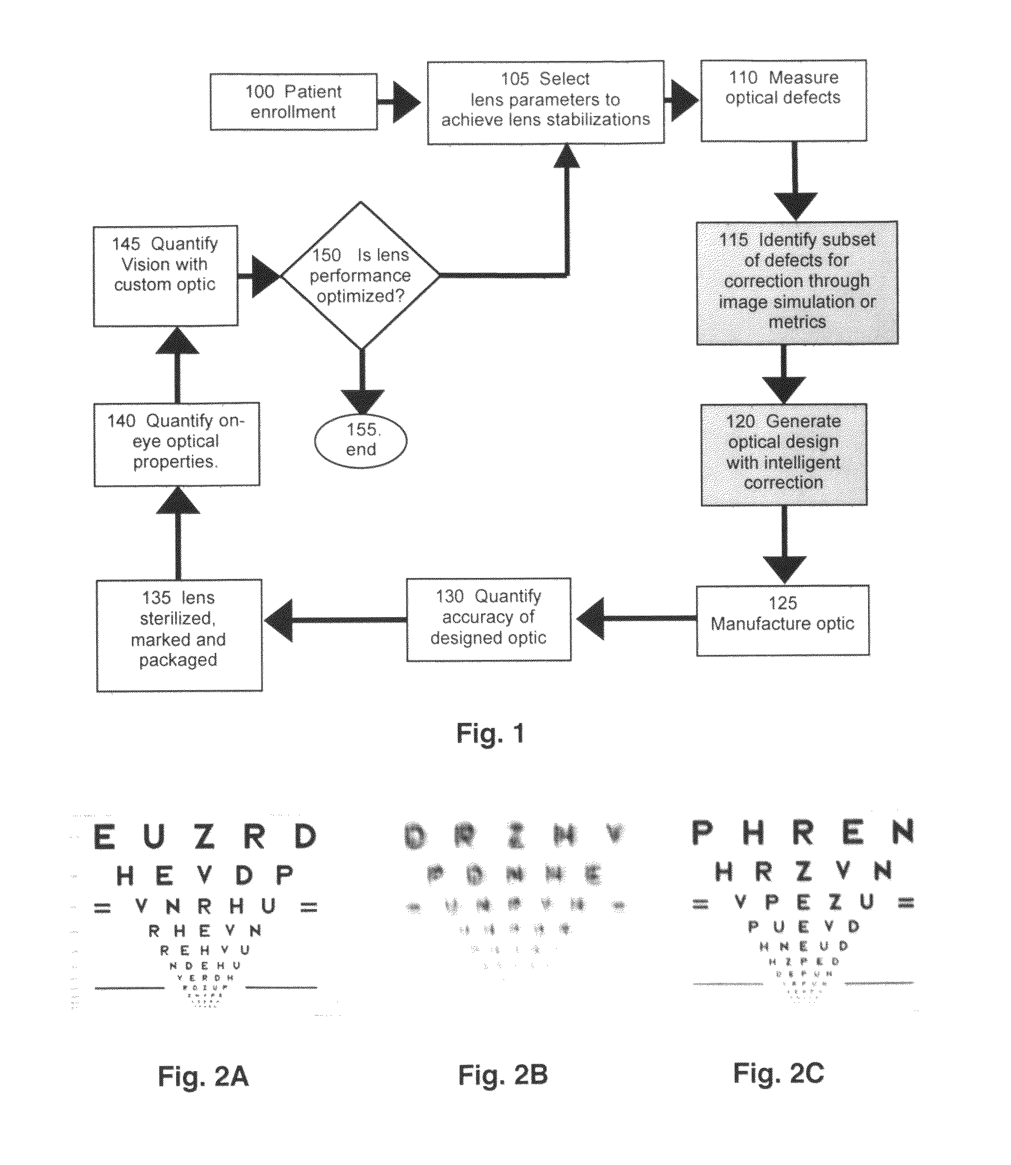
[0053]FIGS. 2A-2B demonstrate the process of image simulation. FIG. 2A shows a non-blurred visual target. FIGS. 2B and 2C show targets that are blurred using image simulation. The process used to form a blurred image is convolution.

[0054]First, the eye's aberrations are used to define a point spread function. This function describes the spatial distribution of a point of light after having been imaged by an optical system. Second, the point spread function is applied to the larger image, which is constructed from a finite number of point sources. The summed impact of distortions caused by the point spread function on all points in the image is seen as the blurred visual target.

[0055]The optical defects used to blur the chart in FIG. 2B provide an idea of how aberrations impact visual performance. FIG. 2C shows a visual target where a subset, but not the complete set, of the optical defects used to blur the image in 2B has been corrected. Note that FIG. 2C is similar ...


PUM


Abstract

Provided herein are methods of manufacturing an optical lens using image simulation and / or predictive metrics to determine optical aberrations and an iterative algorithm to correct the aberrations to create a custom-designed surface for the optical lens and to implement the manufacture of the custom-designed surface onto the lens. Also, a computer program product storing the method is provided. In addition, there are provided a customized optical lens designed by the method and a method of correcting optical aberration to improve visual using the customized optical lens. Further provided is a method of manufacturing a custom lens effective to mimic a subset of optical aberrations.

Description

CROSS-REFERENCE TO RELATED APPLICATIONS[0001]This U.S. national stage application is filed under 35 U.S.C. 363 and claims benefit of priority under 35 U.S.C. 365 of international application PCT / US2006 / 043613, filed Nov. 9, 2006, now abandoned, which claims benefit of priority under 35 U.S.C. 119(e) of provisional U.S. Ser. No. 60 / 734,823, filed Nov. 9, 2005.FEDERAL FUNDING LEGEND[0002]This invention was produced in part using funds obtained through grants NIH / NEI R01 EY05280, NIH / NEI T32 EY07024 and NIH / NEI P30 EY007551 from the National Institutes of Health. Consequently, the federal government has certain rights in this invention.COMPUTER PROGRAM LISTING APPENDIX[0003]Computer program listings are submitted on compact disc in compliance with 37 C.F.R. §1.96 and are incorporated by reference herein. A total of two (2) compact discs (including duplicates) are submitted herein. The files on each compact disc are listed below, but are in text format:[0004]SizeFiles(KB)Date CreatedZer...

Claims


Application Information

Patent Timeline
Patent Type & Authority Patents(United States)
IPC IPC(8): A61B3/00G02C7/02G02C7/04
CPCG02C7/04G02C7/027G02C7/028G02C7/047G02C7/048G02C2202/22
Inventor APPLEGATE, RAYMOND A.MARSACK, JASON D.PESUDOVS, KONRAD
Owner UNIV HOUSTON SYST
Why Eureka
Try Eureka