Linear light source device and planar light source device

a light source device and planar light source technology, applied in lighting support devices, lighting and heating apparatuses, instruments, etc., can solve the problems of light guiding plate deformation, light guiding plate deformation, light guiding plate deformation, etc., to suppress the effect of suppressing the heat loss of light guiding pla

Inactive Publication Date: 2015-05-05
TOYODA GOSEI CO LTD
View PDF19 Cites 6 Cited by
  • Summary
  • Abstract
  • Description
  • Claims
  • Application Information

AI Technical Summary

Benefits of technology

[0015]The object of the present invention is to solve the problems of the prior art by providing a linear light source device that can be used to form the planar light source device free of degradation in the light guiding plate. As another object, the present invention provides a planar light source device with the linear light source device combined with a light guiding plate, and it is possible to suppress degradation in the light guiding plate.
[0024]According to this invention, even when a linear light source device is arranged so that it is pressed to contact the side surface of the light guiding plate for correcting the warp of the linear light source device, an air layer is still formed between the sealing resin and the light guiding plate so that the sealing resin and the light guiding plate are not in contact with each other due to the convex portion of the reflector or the spacer. Consequently, conduction of heat to the light guiding plate from the light emitting elements can be suppressed, and heat degradation of the light guiding plate can be suppressed.

Problems solved by technology

As a result, close contact property on the light guiding plate degrades, and the light incidence efficiency to the light guiding plate decreases.
However, when the linear light source device is arranged so that it is pressed on the light guiding plate to correct the warp of the linear light source device, there is a problem that the light guiding plate degrades due to the heat generated by the linear light source device.
Also, the method described in Patent Reference 2 has insufficient effect in preventing warp.
The LED package described in Patent Reference 3 is not a linear light source device, and the convex portion arranged on the upper surface of the substrate cannot solve the problem.

Method used


Image

  • Linear light source device and planar light source device
  • Linear light source device and planar light source device
  • Linear light source device and planar light source device

Examples


embodiment 1

(Embodiment 1)

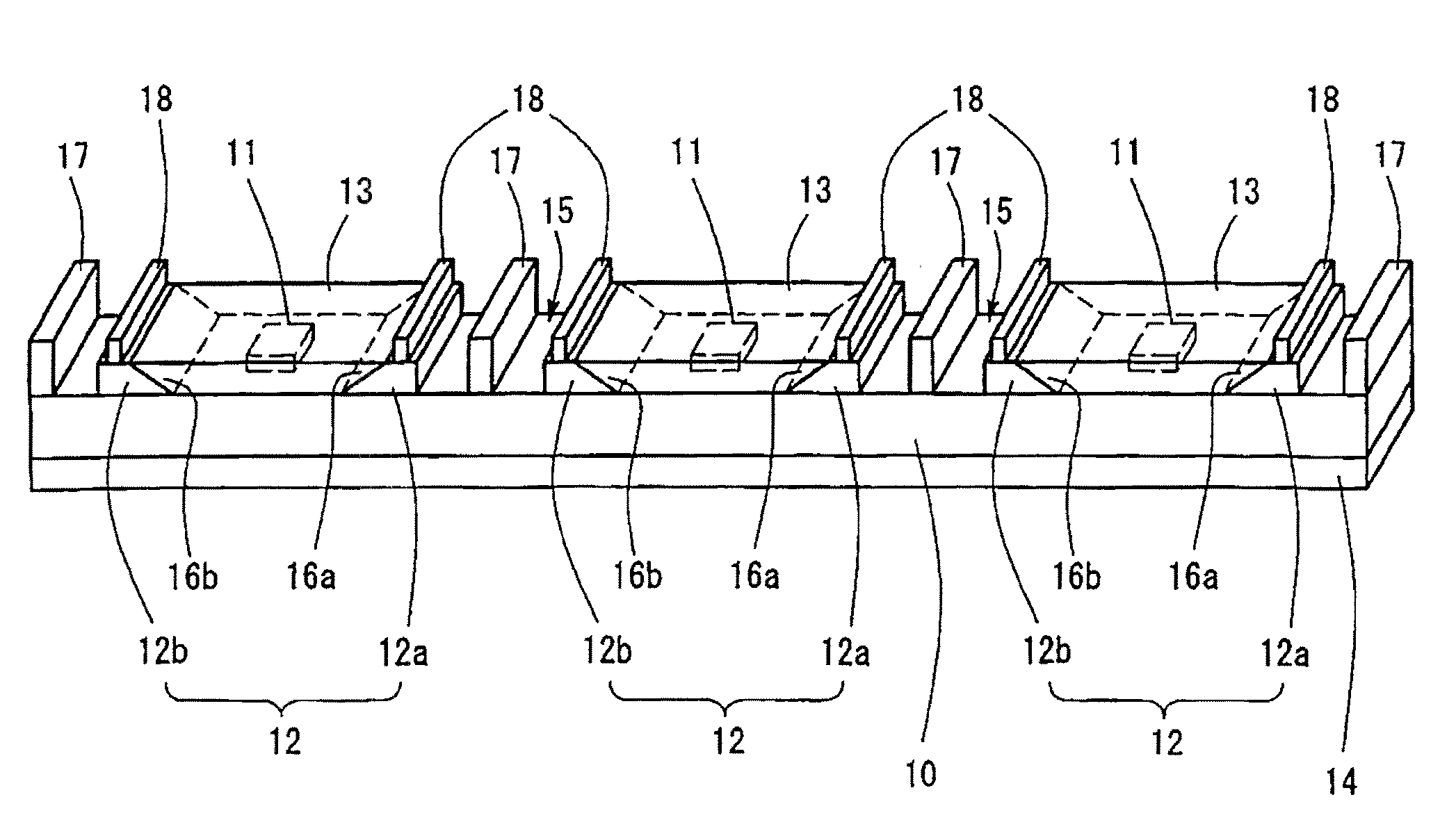
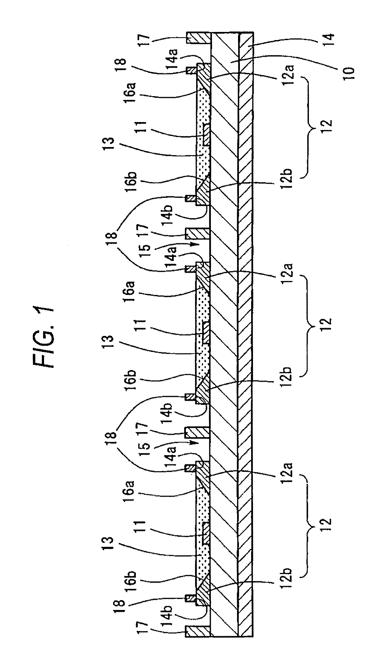
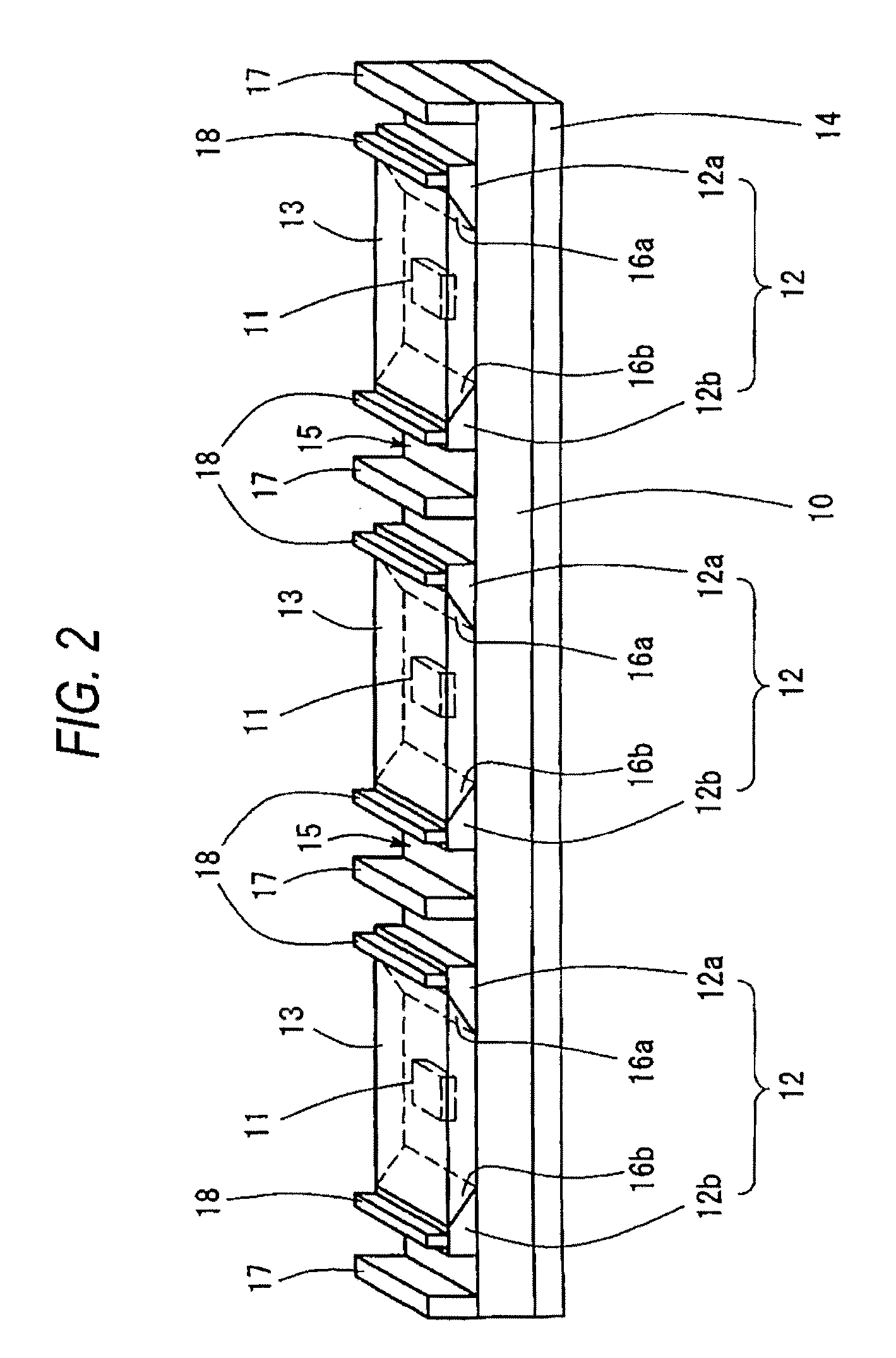
[0031]The linear light source device 1 of Embodiment 1 is the light source arranged on the side surface of the light guiding plate to form a planar light source device. FIG. 1 is a diagram illustrating the configuration of the linear light source device 1 of Embodiment 1. FIG. 2 is an oblique view. As shown in FIGS. 1 and 2, the linear light source device 1 in Embodiment 1 includes a wiring substrate 10 in a slender rectangular shape, light emitting elements 11 arranged in a linear configuration on the wiring substrate 10, reflectors 12 arranged on the wiring substrate 10 for each of the light emitting elements, respectively, a sealing resin 13 for sealing the light emitting elements 11, and the spacers 17.

[0032]The wiring substrate 10 is a FR-5 substrate made of glass cloth base material. One may also use the FR-4 substrate or the like. A wiring pattern is formed on the surface of the wiring substrate 10, and the wiring pattern and the light emitting elements 11 are c...


PUM


Abstract

A linear light source device comprises a wiring substrate in a rectangular shape and a wiring pattern formed thereon, a plurality of light emitting elements arranged on the wiring substrate in a longitudinal direction of the wiring substrate and connected with the wiring pattern on the wiring substrate, reflectors, each of which includes two parts having slope surfaces on one side and the other side facing each other in the longitudinal direction of each light emitting element, and which are separated from each other on the wiring substrate corresponding to the light emitting elements, respectively; and a sealing resin sealing the light emitting elements by burying a recession portion defined by a surface of the wiring substrate where the light emitting elements are arranged and the two slope surfaces, wherein the two parts of each of reflectors have convex portions on their upper surfaces, respectively.

Description

BACKGROUND OF THE INVENTION[0001]1. Field of the Invention[0002]The present invention relates to a light source device having a plurality of light emitting elements arranged in a linear configuration, and arranged on the side surface of a light guiding plate for making a planar light source device. Also, the present invention relates to a planar light source device.[0003]2. Description of the Related Art[0004]There is a planar light emission light source having a light guiding plate and a linear light source device arranged on the side surface of the light guiding plate (for example, see Patent Reference 1) as the backlight light source of the liquid crystal display panel for use in cell phones or digital cameras, etc.[0005]The linear light source device includes a printed circuit board having a slender rectangular-shaped wiring pattern formed thereon, light emitting elements arranged in plurality separated from each other along the longitudinal direction of the printed circuit boar...

Claims


Application Information

Patent Timeline
Patent Type & Authority Patents(United States)
IPC IPC(8): F21V7/04F21V8/00F21Y103/00
CPCG02B6/0031G02B6/0068G02B6/0073G02B6/0091F21Y2103/003G02B6/0083F21Y2103/10F21Y2115/10
Inventor ITO, YUHKI
Owner TOYODA GOSEI CO LTD
Why Eureka
Try Eureka