
Transmitter, transmission method used by the same, receiver for receiving a radio signal from transmitter and wireless communication system including the same

a transmission method and receiver technology, applied in the field of transmitters, transmission methods used by the same, receivers for receiving radio signals from transmitters and wireless communication systems including the same, can solve problems such as difficulty in applying trellis coded modulation to frame length modulation schemes, no effect of detection and correction of errors, etc., to reduce transmission errors in transmission information

Active Publication Date: 2015-05-05
ATR ADVANCED TELECOMM RES INST INT +1
View PDF6 Cites 2 Cited by
  • Summary
  • Abstract
  • Description
  • Claims
  • Application Information

AI Technical Summary

Benefits of technology

The present invention aims to provide a transmitter that can minimize errors in wireless communication using frame length modulation. Additionally, the invention also aims to reduce transmission errors in transmitting information through the same mechanism.

Problems solved by technology

However, block coding and convolutional coding described in Non-Patent Document 2 do not take error characteristics of the modulation system into account, and therefore there are no effects to detect and correct errors in frame-length-modulated signals with significantly different error characteristics depending on the modulation value.
Since the symbol length is not constant in frame length modulation, it is difficult to apply the trellis coded modulation to a frame length modulation scheme.

Method used


Image

  • Transmitter, transmission method used by the same, receiver for receiving a radio signal from transmitter and wireless communication system including the same
  • Transmitter, transmission method used by the same, receiver for receiving a radio signal from transmitter and wireless communication system including the same
  • Transmitter, transmission method used by the same, receiver for receiving a radio signal from transmitter and wireless communication system including the same

Examples


Embodiment Construction

[0056]Embodiments of the present invention will be described in detail with reference to the drawings. The same or corresponding parts in the drawings are labeled with the same numerals and their description will not be repeated.

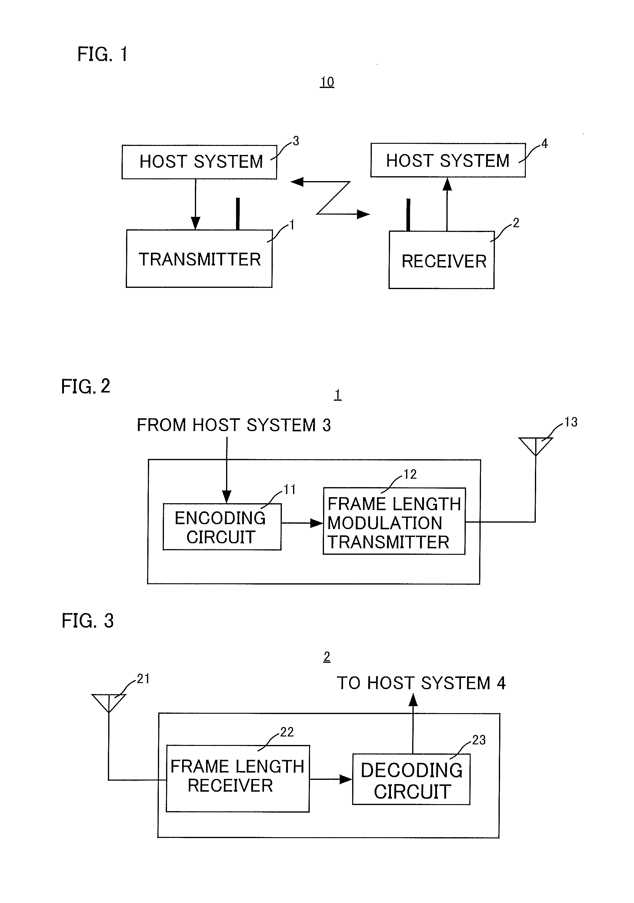
[0057]FIG. 1 is a schematic diagram of a configuration of a wireless communication system according to an embodiment of the present invention. Referring to FIG. 1, a wireless communication system 10 according to an embodiment of the present invention includes a transmitter 1 and a receiver 2.

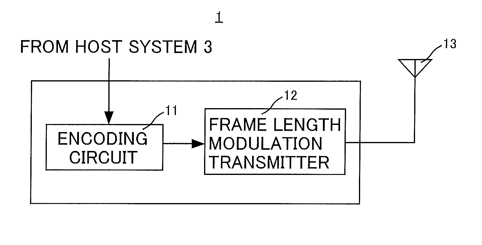
[0058]The transmitter 1 receives transmission information from the host system 3 and frame-length-modulates the received transmission information using the methods described below, and transmits the modulated transmission information via wireless communication.

[0059]The receiver 2 receives a radio signal transmitted from the transmitter 1 and demodulates the received radio signal using the methods described below. The receiver 2 then outputs the demodulated transmission ...


PUM


Abstract

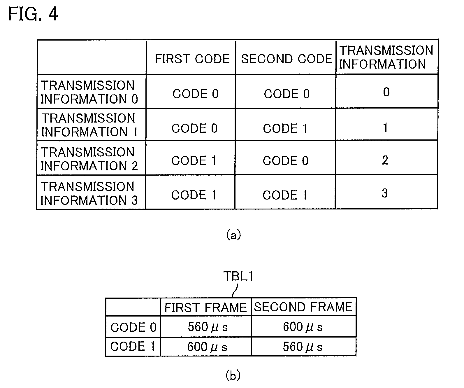
A transmitter incorporates a table (TBL1) for assigning the frame lengths of 560 μs and 600 μs to the code “0” in a binary system and assigning the frame lengths of 600 μs and 560 μs to the code “1” in the binary system. The transmitter refers to the table (TBL1) and assigns the two frame lengths of 560 μs and 600 μs and the two frame lengths of 600 μs and 560 μs to the codes “0” and “1”, respectively, in the code sequences [0,0], [0,1], [1,0] and [1,1] representing the transmission information “0” to “3” represented using the binary system, and sequentially transmits four radio signals having the assigned four frame lengths.

Description

TECHNICAL FIELD[0001]The present invention relates to a transmitter, a transmission method used by the same, a receiver for receiving a radio signal from the transmitter and a wireless communication system including the same.BACKGROUND ART[0002]To enable wireless communication using a transmitter for transmitting a wireless local area network (LAN) signal and a receiver operating at a power consumption that is much lower than typical wireless LAN receivers, Non-Patent Document 1 proposes a frame length modulation scheme where a frame length, which is a time length of a radio frame, is associated with information for communication.[0003]In cable or wireless communication, information that is being transmitted may become erroneous due to noise or the like on the transmission path. In wireless communication, a radio signal may be attenuated depending on the transmission distance or be affected by multipath fading, resulting in significant errors in information.[0004]Various coding meth...

Claims


Application Information

Patent Timeline
Patent Type & Authority Patents(United States)
IPC IPC(8): H04L1/00H04L25/49
CPCH04L1/0083H04L25/49H04L25/4902
Inventor KONDO, YOSHIHISAYOMO, HIROYUKITANG, SUHUAKIMURA, TAKATOSHIIWAI, MASAHITOHARA, YUKIHIROITO, TETSUYA
Owner ATR ADVANCED TELECOMM RES INST INT
Learn More