Circular saw

a circular saw and saw blade technology, applied in the field of circular saws, can solve problems such as time and cost savings, and achieve the effect of reducing the number of work accidents

Inactive Publication Date: 2015-05-12
ROBERT BOSCH GMBH
View PDF16 Cites 0 Cited by
  • Summary
  • Abstract
  • Description
  • Claims
  • Application Information

AI Technical Summary

Benefits of technology

[0013]Thus, in contrast to the related art it is no longer necessary to uninstall the splitting wedge to carry out certain work operations. Instead, the splitting wedge may be conveniently moved by the operator into appropriate positions, depending on the work operation to be carried out. On the one hand this results in time and cost savings, and on the other hand due to the ease of handling it is more likely that the operator moves the splitting wedge back to the safe proper position as soon as a work operation which is not possible using a properly installed splitting wedge is completed. The safety of the circular saw may accordingly be increased.
[0015]In addition, at least one retaining arrangement may be provided which is designed in such a way that it is able to fix the first splitting wedge in at least one position. Such fixing is intended to prevent the splitting wedge from inadvertently leaving a defined position.
[0019]For this purpose a pretensioning arrangement, for example, may be provided which, starting from the second position, pretensions the first splitting wedge toward the proper position and automatically transfers the first splitting wedge to the proper position as soon as a workpiece material is no longer present in the region in which the splitting wedge is in its proper position. It may thus be ensured that the splitting wedge is immediately transferred to the proper position which is safe for the operator as soon as this is possible. If, for example, an inset cut is to be made on a workpiece, first the splitting wedge is transferred manually or with the aid of appropriate drive arrangement from the proper position to the second position, and is fixed in this second position, optionally using the at least one retaining arrangement. The saw blade of the circular saw is then brought into contact with the workpiece. As soon as the workpiece is situated above the splitting wedge and is able to counteract the pretensioning of the pretensioning arrangement on account of its own weight, the fixing of the splitting wedge in the second position performed by the retaining arrangement may be removed manually or automatically. After the fixing performed by the retaining arrangement is released, the pretensioning arrangement pushes the splitting wedge toward the workpiece. When the splitting wedge thus engages with the incision provided in the workpiece, or the end of the workpiece is reached in the region of the splitting wedge, the pretensioning arrangement pushes the splitting wedge into the proper position. In other words, the splitting wedge is transferred to the safe proper position as soon as this is possible. The period of time during which an operator is endangered by an unguided and / or exposed saw blade may thus be reduced to a minimum, thus allowing the number of work accidents to be reduced.

Problems solved by technology

On the one hand this results in time and cost savings, and on the other hand due to the ease of handling it is more likely that the operator moves the splitting wedge back to the safe proper position as soon as a work operation which is not possible using a properly installed splitting wedge is completed.

Method used


Image

  • Circular saw
  • Circular saw
  • Circular saw

Examples


Embodiment Construction

[0040]Identical or corresponding components are denoted below by the same reference numerals.

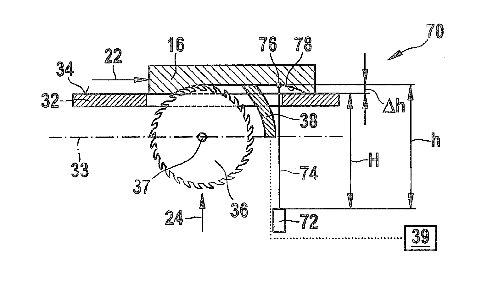
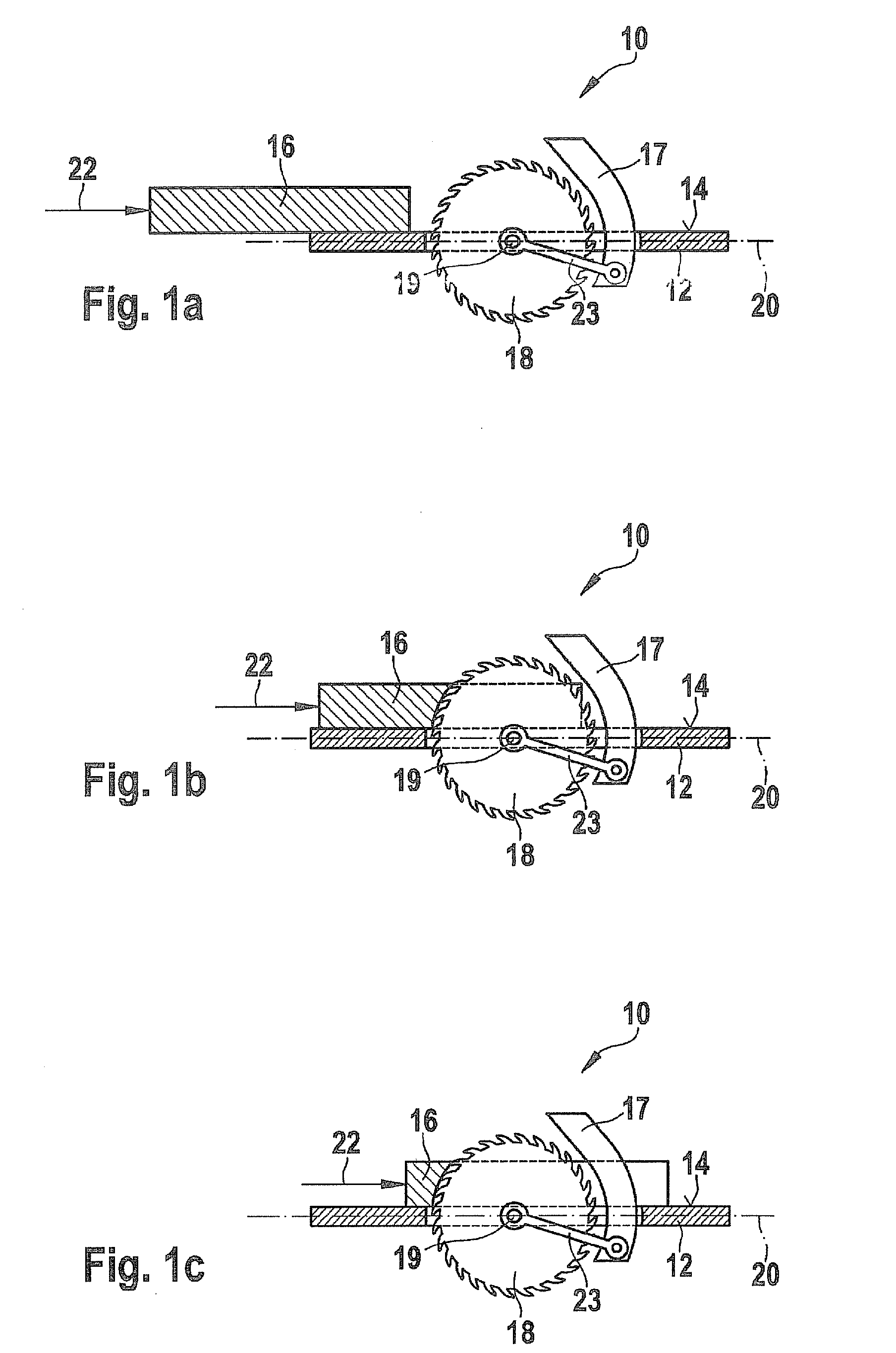
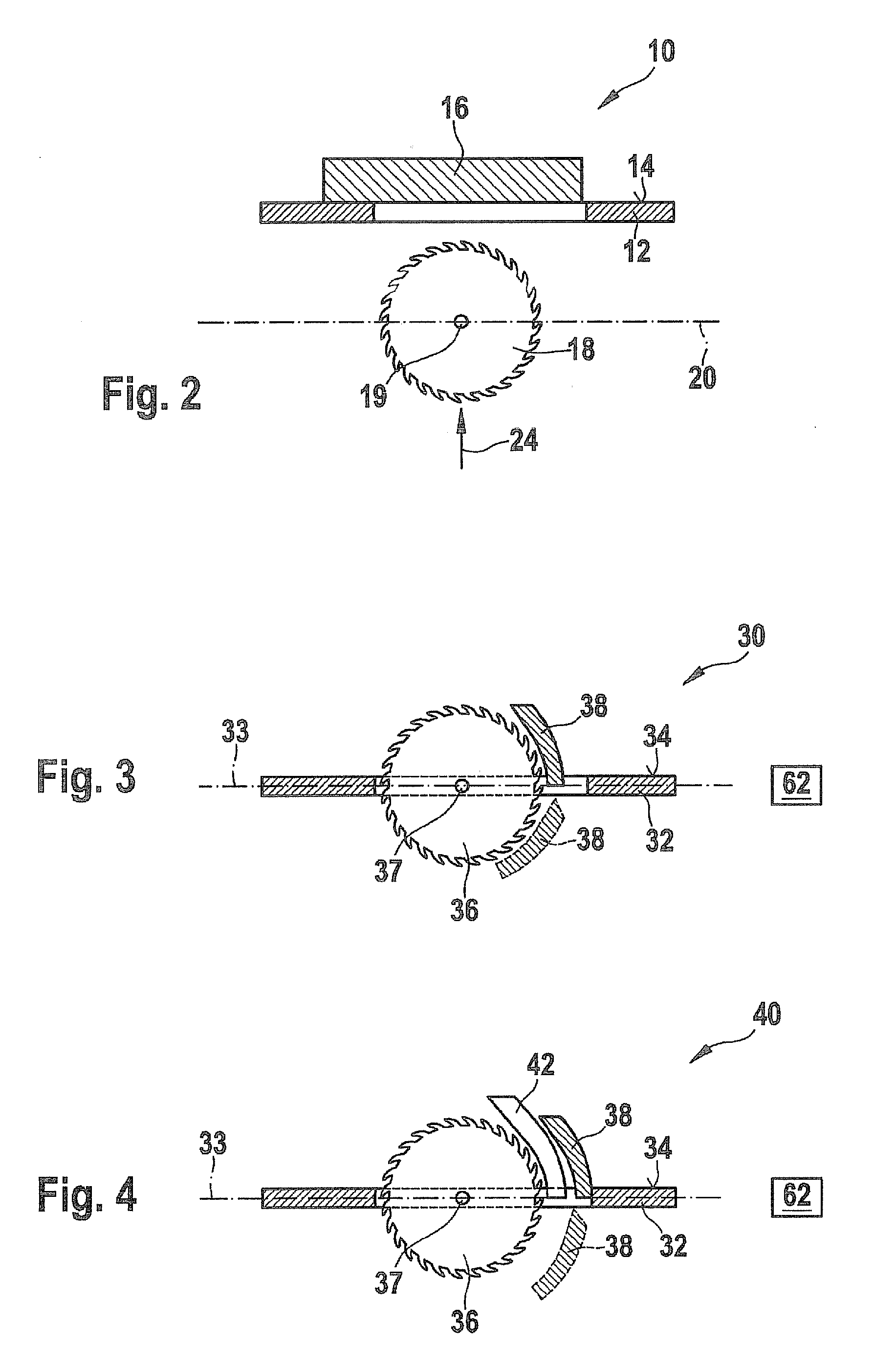
[0041]FIGS. 1a, 1b, and 1c show schematic views of states of a conventional table circular saw while a through cut is being made in a workpiece, the cut being made in the workpiece starting from the edge of the workpiece. The table circular saw, which is denoted in general by reference numeral 10 in the stated figures, includes a saw table 12 having a workpiece support surface 14 on which a workpiece 16 is positioned. Table circular saw 10 also includes a saw blade 18, which with the aid of a motor (not illustrated) may be rotationally driven about a rotational axis 19 which does not rotate, and moved up and down. The saw blade may also be swiveled about an axis 20 in a known manner to make angled cuts. A splitting wedge 17 which is used for guiding workpiece 16 and protecting the operator is situated behind saw blade 18 as viewed by the user (to the right in FIGS. 1a through 1c) when table ...


PUM

PropertyMeasurementUnit
angleaaaaaaaaaa
angleaaaaaaaaaa
distanceaaaaaaaaaa

Abstract

A circular saw including a saw blade (36) which may be rotatingly driven about a rotational axis, and at least one first splitting wedge is described. The circular saw is configured so that the first splitting wedge is movable relative to the rotational axis of the saw blade.

Description

FIELD OF THE INVENTION[0001]The present invention relates to a circular saw having a saw blade and a splitting wedge.BACKGROUND INFORMATION[0002]Circular saws of the aforementioned type are in various embodiments in the related art.[0003]German patent document DE 295 10 061 U1, for example, discusses a hand-held circular saw having a housing on which a base plate having a workpiece support is pivotably mounted. A saw blade together with the associated motor unit is accommodated in the housing in a known manner, it being possible with the aid of the motor unit to rotatingly drive the saw blade about a rotational axis which does not rotate. The saw blade may be moved through the base plate in such a way that the saw blade projects from the workpiece support surface in order to engage with a workpiece situated on the workpiece support surface. At the rear region of the housing, a splitting wedge support is positioned which is fixedly mounted with respect to the rotational axis of the s...

Claims


Application Information

Patent Timeline
Patent Type & Authority Patents(United States)
IPC IPC(8): B27G19/08B27G19/02
CPCB27G19/02B27G19/08Y10T83/2077Y10T83/85Y10T83/6657
Inventor SIMON, STEPHAN
Owner ROBERT BOSCH GMBH
Why Eureka
Try Eureka