Bustle pipe arrangement

a bustle pipe and arrangement technology, applied in the direction of lighting and heating apparatus, charge manipulation, furnaces, etc., can solve the problems of difficult to adapt to existing shaft furnaces, difficult to arrange at the level of the lower shaft, and limited injection points of the bustle pipe arrangement, etc., to achieve the effect of increasing the operational flexibility of the shaft furnace, increasing the flow rate, and flexible gas injection through the present bustle pipe arrangemen

Active Publication Date: 2015-05-12
PAUL WURTH DEUT GMBH +1
View PDF22 Cites 0 Cited by
  • Summary
  • Abstract
  • Description
  • Claims
  • Application Information

AI Technical Summary

Benefits of technology

[0009]Due to the plurality of first and second support arms arranged on two separate levels, the bustle pipe arrangement is self-supporting; in fact the bustle pipe arrangement is supported directly on the wall of the shaft furnace and no frame construction is necessary to support the bustle pipe arrangement. Furthermore, as the bustle pipe is directly connected to the shaft furnace wall, compensators are not necessary. This lowers the risk of leakages between the bustle pipe and the shaft furnace. The more compact design of the bustle pipe arrangement also allows for the number of injection points to be considerably increased when compared to conventional bustle pipe arrangements. The increased number of injection points allows a more homogenous injection of gas into the shaft furnace. A further important advantage of the present bustle pipe arrangement is that it can be easily integrated on existing shaft furnaces, with minimal alterations to the shaft furnace.
[0011]The second blow channels arranged through the second support arms allow the injection of gas, air or reduction gas, into the shaft furnace on two separate levels. This leads to a higher number of injection points and to a more homogeneous repartition of gas injected.
[0014]The access ports also allow the plugging of individual blow channels, thereby rendering the gas injection through the present bustle pipe arrangement particularly flexible. Indeed, a plunger may be associated with an access port for at least partially plugging a respective blow channel. The use of such a plunger allows the plugging of certain blow channels, thereby increasing the flow rate through the remaining blow channels. It may e.g. be desired to inject gas into the shaft furnace at one level. All of the blow channels of the other level are then plugged. The plunger may also have conical nose for allowing regulation of gas flow through a respective blow channel.
[0015]The access ports also provide access to injection nozzles, which may be removably installed in the blow channels, preferably in the end of the blow channels facing the shaft furnace. This allows replacing worn injection nozzles or exchanging injection nozzles of a particular inside diameter with injection nozzles of a different inside diameter. As an alternative, nozzle inserts may be inserted into the injection nozzles through the access ports. Such nozzle inserts would also change the inner diameter of the injection nozzle. The possibility to change the inside diameter of the injection nozzle allows the flow of hot gas through the blow channels to be adapted to particular operating conditions, thereby increasing the operational flexibility of the shaft furnace.
[0019]The first and / or second support arms may be formed by a piece of piping, lined internally with refractory material and having the first and second blow channels passing therethrough. The piece of piping is advantageously a straight piece of piping. Such a straight piece of piping provides a direct connection between the bustle pipe and the interior of the shaft furnace, i.e. without bends, joints or connections. The pressure loss across the piece of piping can thereby be reduced.
[0021]According to a preferred embodiment of the invention, the second support arms are arranged at an angle chosen such that access ports associated with the second blow channels are essentially on the same level as access ports associated with the first blow channels. The second support arms may e.g. be arranged at an angle of about 45° with respect to the horizontal and an imaginary line between the second support arm and its associated access port may pass through the centre of the bustle pipe. Arranging all access ports, i.e. those associated with both the first and second blow channels, on a same level allows for an easier and quicker servicing of the blow channels. Indeed, a single platform may be used to access both levels of injection points for servicing. Furthermore, it should also be noted that an increased angle provides an improved support for the bustle pipe arrangement.

Problems solved by technology

Indeed, the considerable weight of this arrangement makes it difficult to arrange at the level of the lower shaft.
Also, the cumbersome design of the conventional bustle pipe arrangement limits the number of injection points.
However, this solution is difficult to adapt to existing shaft furnaces and introduces some additional risks as to wear of the refractory material, in particular in the wall separating the distribution channel from the furnace chamber.
Indeed, the structure of the furnace is weakened by the “Midrex”-type construction.

Method used


Image

  • Bustle pipe arrangement
  • Bustle pipe arrangement
  • Bustle pipe arrangement

Examples


Embodiment Construction

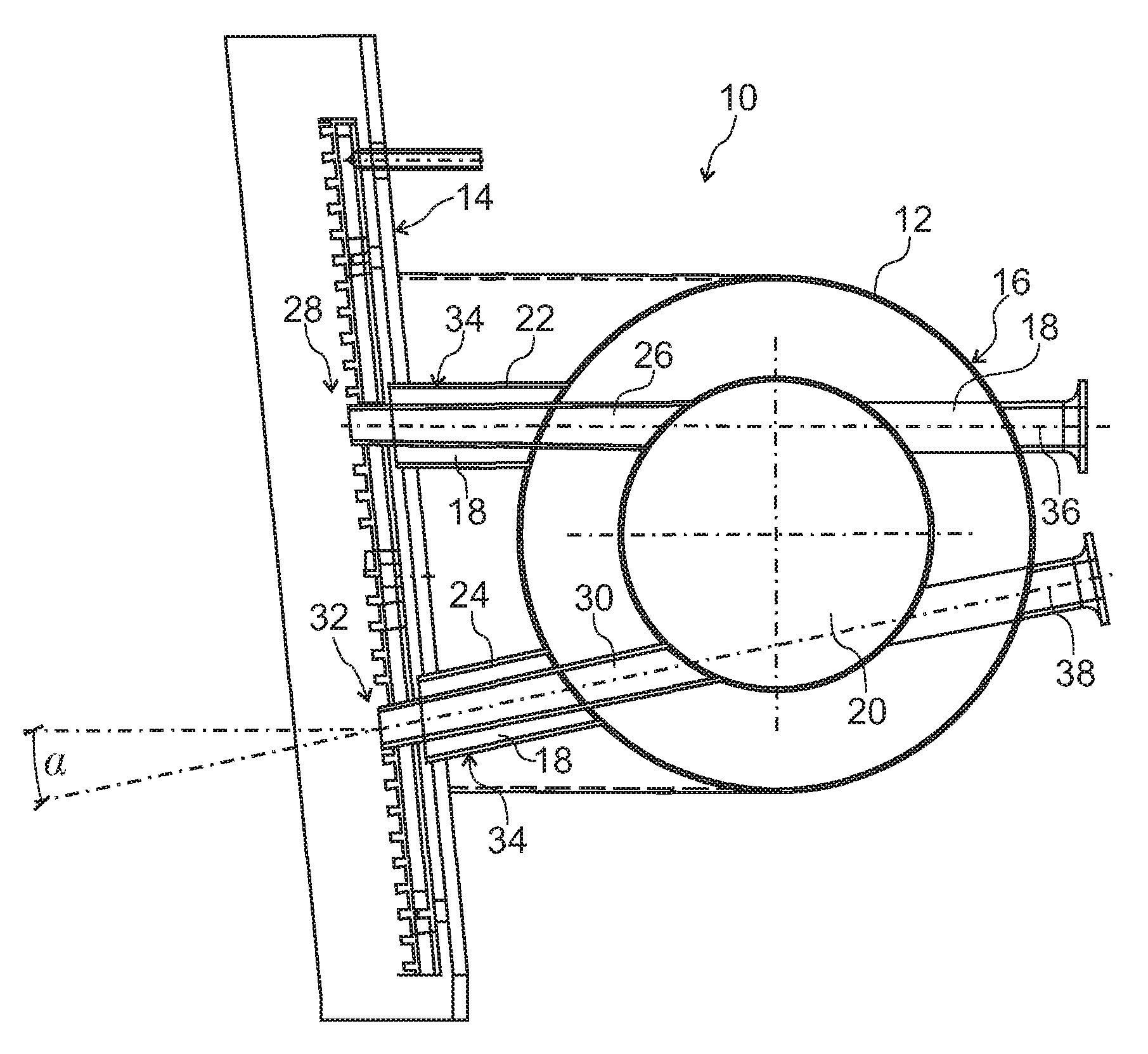
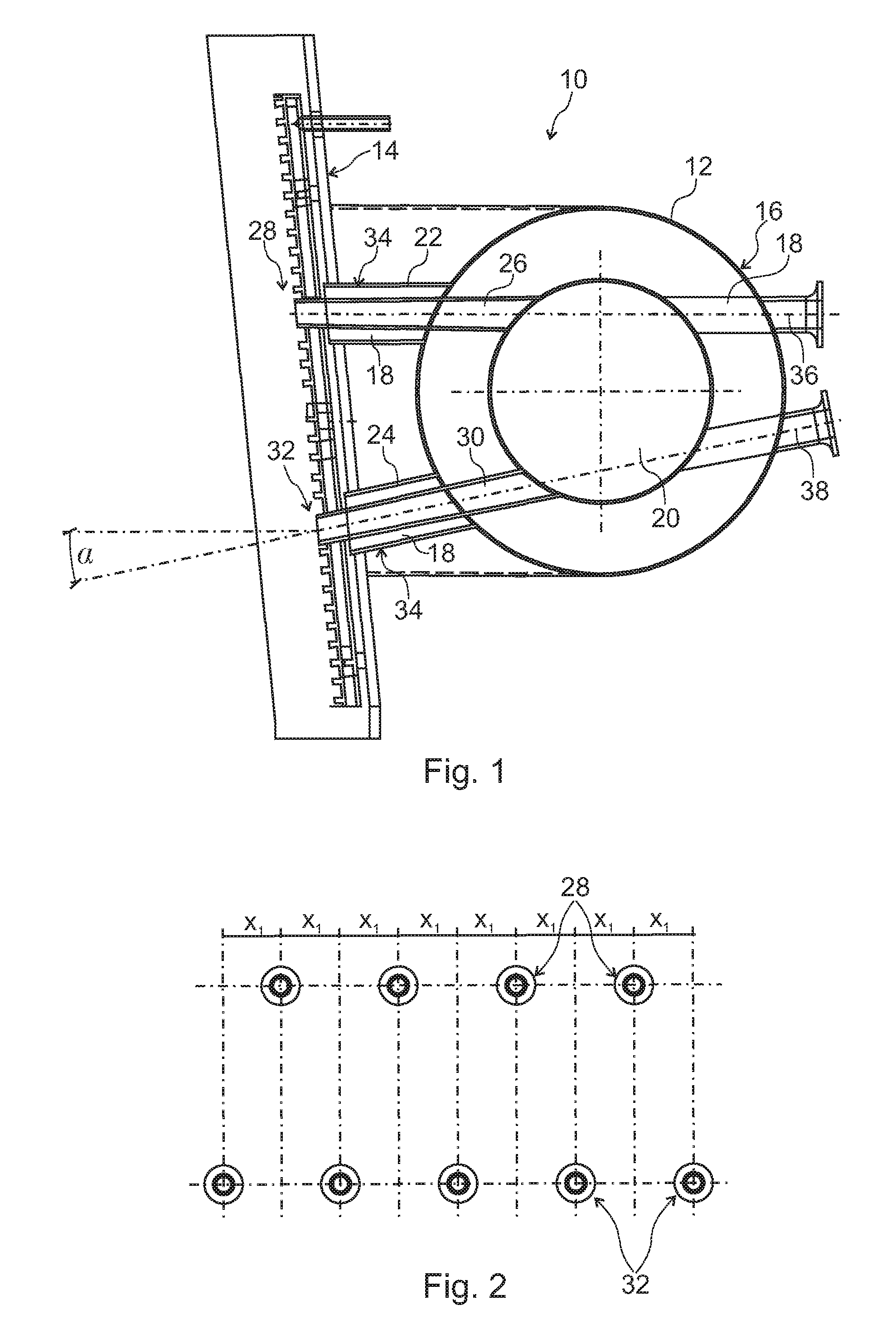
[0029]The present invention is illustrated by referring to FIG. 1, which shows a bustle pipe arrangement, which is arranged around an outer casing of a shaft furnace.

[0030]The bustle pipe arrangement 10 comprises a bustle pipe 12, circumferentially arranged around a shaft furnace, a portion of an outer casing 14 of which is shown in FIG. 1. The bustle pipe 12 is arranged at a certain distance from the outer casing 14 and is formed by a pipe 16 of essentially round cross-section, which is internally lined with refractory material 18 within which a gas channel 20 is formed.

[0031]The bustle pipe 12 is maintained in place along the outer casing 14 of the shaft furnace by means of a plurality of first support arms 22 arranged at a first level and second support arms 24 arranged at a second level. The first and second support arms 22, 24 are arranged all around the circumference of the shaft furnace and support the bustle pipe 12. The support arms 22, 24 are preferably attached to the bus...


PUM

PropertyMeasurementUnit
angleaaaaaaaaaa
angleaaaaaaaaaa
angleaaaaaaaaaa

Abstract

There is provided a bustle pipe arrangement of a shaft furnace, in particular for feeding hot gas into the shaft furnace such as e.g. a blast furnace, wherein the bustle pipe arrangement comprises a circumferential bustle pipe arranged along the outer casing of the shaft furnace, at a certain distance therefrom. The arrangement further comprises a plurality of first support arms connecting the bustle pipe to the outer casing of the shaft furnace on a first level; and a plurality of second support arms connecting the bustle pipe to the outer casing of the shaft furnace on a second level, the first level being separate from the second level. The first and second support arms are configured to support the circumferential bustle pipe. First blow channels are arranged through the first support arms for fluidly connecting the bustle pipe to the interior of the shaft furnace.

Description

TECHNICAL FIELD[0001]The present invention generally relates to a bustle pipe arrangement, in particular for feeding pressurized hot gas to a shaft furnace.BACKGROUND[0002]In shaft furnaces, particularly in blast furnaces, pressurized hot gas, typically pressurized hot air, is blown into the furnace for aiding the reduction of ore in the shaft furnace.[0003]Conventionally, a circumferential bustle pipe is arranged in the tuyere band around the outer casing of the shaft furnace, at a certain distance therefrom. The gas is fed from the bustle pipe through a tuyere stock row, where it is blown into the shaft furnace. A tuyere stock is generally provided with compensators for compensating for relative movement between the bustle pipe and the shaft furnace. Such a conventional bustle pipe arrangement is e.g. known from WO 86 / 05520.[0004]It has been suggested to inject gas into the shaft furnace, not only at the upper hearth level, but also in a region above the melting zone, also referre...

Claims


Application Information

Patent Timeline
Patent Type & Authority Patents(United States)
IPC IPC(8): C21B7/16C21B9/10F27B1/12F27B1/16F27D1/12F27D3/16
CPCC21B7/163C21B9/10F27B1/12F27B1/16F27D1/12F27D3/16
Inventor SIMOES, JEAN-PAULHAUSEMER, LIONELMOLLER, MANFREDTOCKERT, PAULHEBEL, RUDOLF
Owner PAUL WURTH DEUT GMBH
Why Eureka
Try Eureka