Magnetic and/or electrostatic pivot

a technology of magnetic and/or electrostatic pivots and pivots, which is applied in the direction of bearings, physics instruments, repair tools, etc., can solve the problems of weak dependence of the efficiency and/or quality factor is considerably lower, so as to improve the independence of the operating quality of the timepiece movement and reduce the friction

Active Publication Date: 2015-05-12
MONTRES BREGUET
View PDF15 Cites 10 Cited by
  • Summary
  • Abstract
  • Description
  • Claims
  • Application Information

AI Technical Summary

Benefits of technology

[0019]The invention proposes to overcome the problems of the prior art, by inventing a method for orienting a timepiece component, and more specifically aligning the component on a pivot axis, allowing friction to be drastically reduced compared to ordinary mechanical guide devices, and thereby improving the independence of the operating quality of a timepiece movement with respect to the orientation thereof in space.
[0020]To achieve this, the invention implements a device for guiding the pivoting of the component, so as to form a magnetic pivot for timepiece components providing efficiency and / or a quality factory that is independent of position.

Problems solved by technology

In the particular application to a pivoting component incorporated in a watch movement, or in an oscillator, a recurring problem lies in the strong dependence of the efficiency and / or quality factor of the component on the position of the watch in which said component is incorporated.
In particular, the efficiency and / or quality factor is considerably lower when a watch is in a vertical position.
However, the holding of the mobile component on the first magnetic pole piece is not equivalent to a support since there is a connection between this mobile component and the internal tubular magnet, via a flange and one of the two sleeves.

Method used


Image

  • Magnetic and/or electrostatic pivot
  • Magnetic and/or electrostatic pivot
  • Magnetic and/or electrostatic pivot

Examples


Embodiment Construction

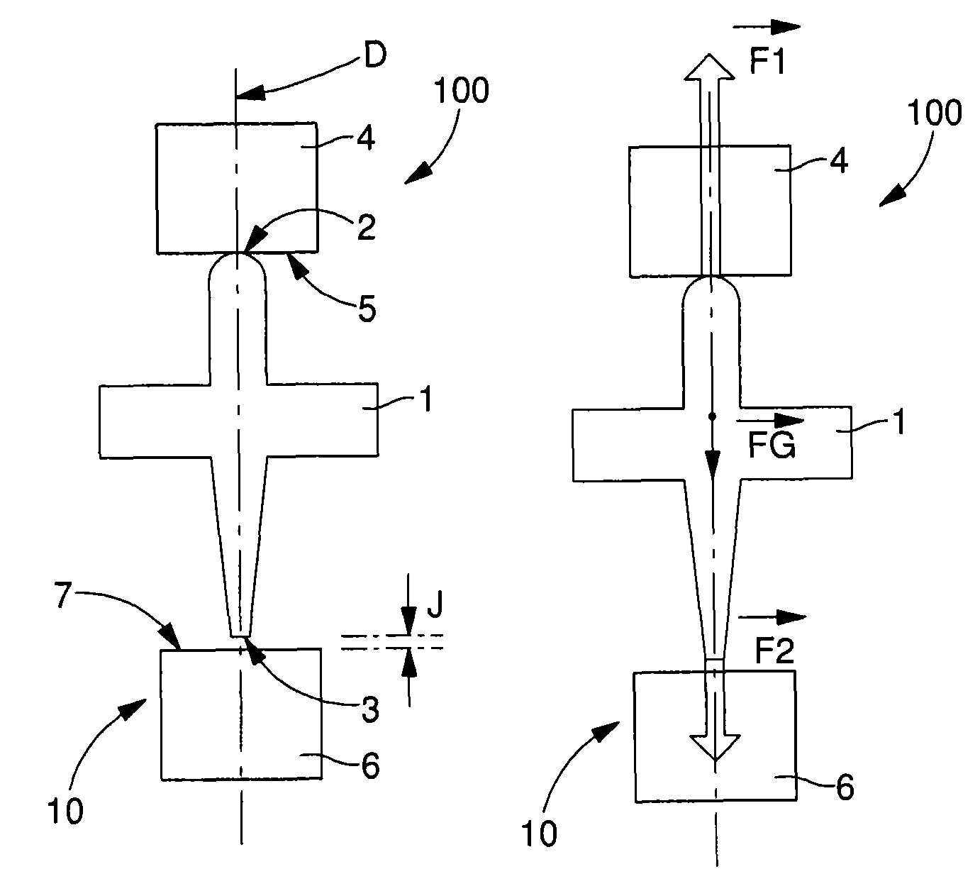
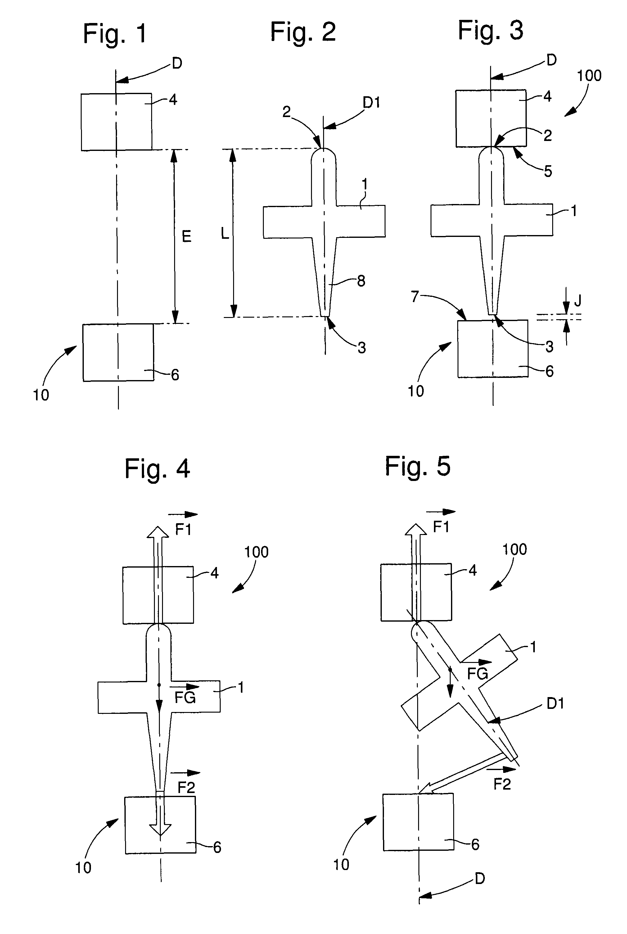
[0041]The invention develops a particular method for orienting a timepiece component 1 to guide the pivoting thereof, and, more specifically, for aligning said component on a pivot axis D.

[0042]The object of the invention is to provide an alternative to conventional pivots, and to drastically reduce friction compared to ordinary mechanical guide devices, and thereby improve the independence of the operating quality of a timepiece movement relative to the orientation thereof in space.

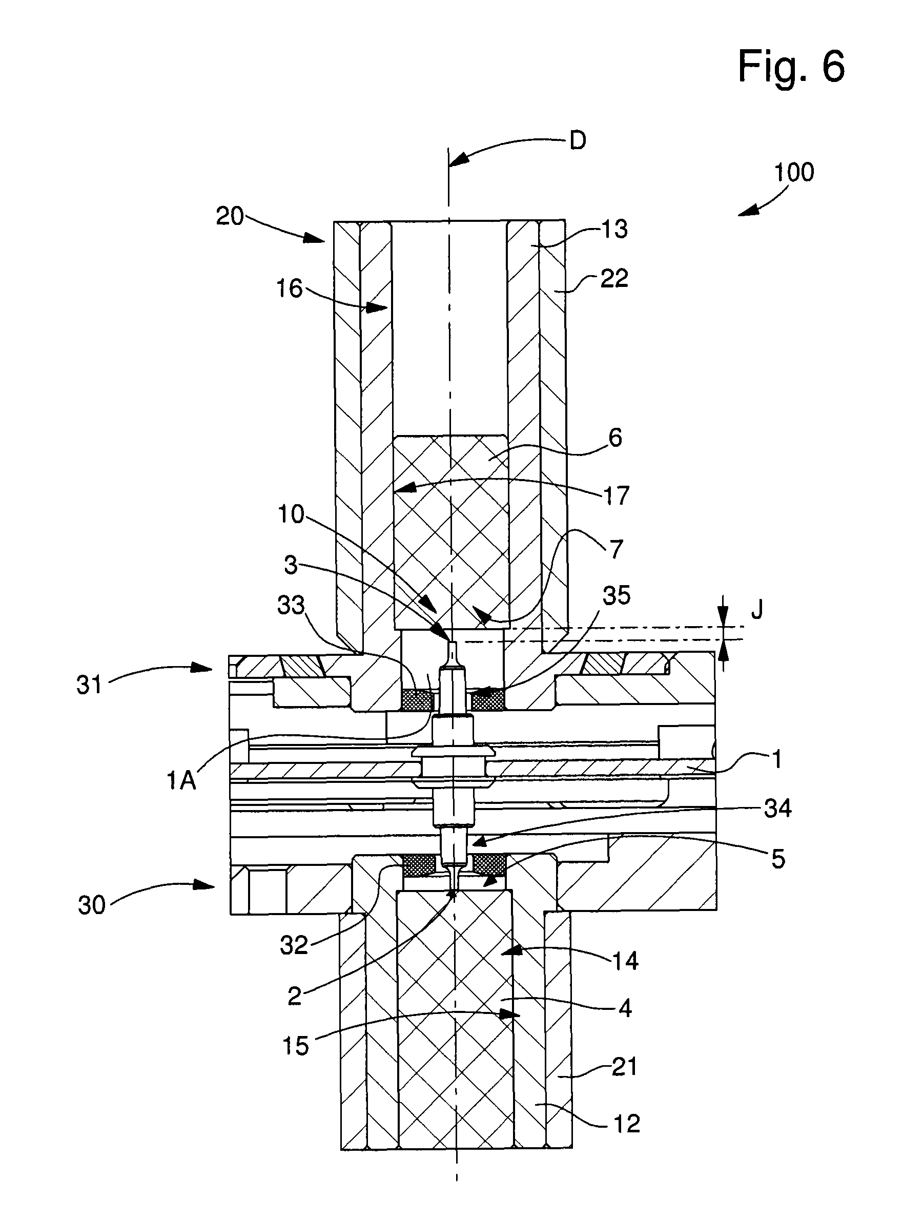
[0043]In order to implement this method, the invention further concerns a device for guiding the pivoting of the component, so as to form a magnetic and / or electrostatic pivot for timepiece components providing efficiency and / or a quality factor that is independent of position.

[0044]Owing to certain particular features, which will be set out hereinafter, notably the preferred use of highly intense magnetic and / or electrostatic forces relative to the force of gravity, the invention finds more particular a...


PUM

PropertyMeasurementUnit
remanent magnetic fieldaaaaaaaaaa
electrostatic fieldsaaaaaaaaaa
magneticaaaaaaaaaa

Abstract

A method and device for orienting a timepiece component on both ends of which two magnetic / electrostatic fields each attract it onto a pole piece, with an unbalance in the intensity of the fields around the component, in order to create a differential in the forces thereon and to press one of the ends onto a contact surface of one of the pole pieces, and to hold the other end at a distance from the other pole piece. A magnetic / electrostatic pivot includes such a component with two ends. It includes a guide device with surfaces of two pole pieces each attracted by a magnetic / electrostatic field transmitted by one of the ends, or generating a magnetic / electrostatic field attracting one of the ends, the magnetic / electrostatic forces exerted on the two ends are of different intensity, in order to attract only one end into contact with only one of the pole piece surfaces.

Description

FIELD OF THE INVENTION[0001]The invention concerns a method of orienting a timepiece component to guide the pivoting of said component, which is made of material that is at least partially magnetically permeable or at least partially magnetic, and / or of material that is at least partially conductive or respectively at least partially electrized, wherein said component is pivotally mounted in a chamber between a first end and a second end of said component.[0002]The invention also concerns a device for guiding the pivoting of a timepiece component, which is made of material that is at least partially magnetically permeable or at least partially magnetic, and / or of material that is at least partially conductive or at least partially electrized, at a first end and at a second end.[0003]The invention also concerns a magnetic and / or electrostatic pivot including a timepiece component, made of a material that is at least partially magnetically permeable or at least partially magnetic at a...

Claims


Application Information

Patent Timeline
Patent Type & Authority Patents(United States)
IPC IPC(8): G04B17/32H02K7/09G04B31/00F16C32/04
CPCF16C32/0408Y10T29/49579G04B31/00G04B17/32F16C25/045F16C2370/00G04B31/004G04B15/14G04C3/064G04C5/005H02K7/09
Inventor MARECHAL, SYLVAINSARCHI, DAVIDEKARLEN, OLIVIERTODESCHINI, ARNAUD
Owner MONTRES BREGUET
Why Eureka
Try Eureka