Air spring

a technology of air springs and springs, which is applied in the field of air springs, can solve the problems of inability to make the rigidity of the shoulder portion sufficiently high, the shoulder portion becomes inability to withstand the restorative force and the linkage portion cannot be formed from different types of materials, so as to prevent the deterioration of the lifespan of the dust cover due to such deformation, the linkage strength of the bellows portion and the circular tube can

Active Publication Date: 2007-09-06
PROSPIRA CORP
View PDF3 Cites 9 Cited by
  • Summary
  • Abstract
  • Description
  • Claims
  • Application Information

AI Technical Summary

Benefits of technology

[0033] With the above-described embodiments, even in a case where the amount of restriction of the band was made sufficiently large, by narrowing the opening width of the slit in accordance with the amount of constriction of the band, the occurrence of wrinkles and slackening in the circular tube and the fitting portion at the dustcover is prevented, so when the linking portion is fixed to the circular tube using the band, the operational qualities thereof can be made favorable. Further, the linking strength of the bellows portion and the circular tube can be increased.
[0034] With the air spring according to the present invention as explained above, flex deformation of the shoulder portion due to the restorative force of the bellows portion at the time of compression thereof in the dustcover can be prevented, and deterioration of the lifespan of the dustcover due to such deformation can thus be prevented.

Problems solved by technology

Also, the linking portion, the shoulder portion, and the bellows portion cannot be formed from different types of materials where their respective specific intensities differ.
For this reason, when forming the dustcover, it becomes difficult to make the rigidity of the shoulder portion sufficiently high when the flexibility of the bellows portion in the extending / contracting directions has been made high for the sake of ensuring good following qualities of the dustcover relative to the moving body (i.e., the suspension arm).
With the above-described air spring, when the rigidity of the shoulder portion in the dustcover is insufficient, the shoulder portion becomes unable to withstand the restorative force of the bellows portion at the time of suspension arm bounding, i.e., when the bellows portion is compression deformed.
If this type of straining deformation occurs repeatedly at the shoulder portion, damage such as cracks and the like tend to occur in the shoulder portion in a relatively short period of time, and this can decrease the lifespan of the dustcover.

Method used


Image

  • Air spring
  • Air spring
  • Air spring

Examples


first exemplary embodiment

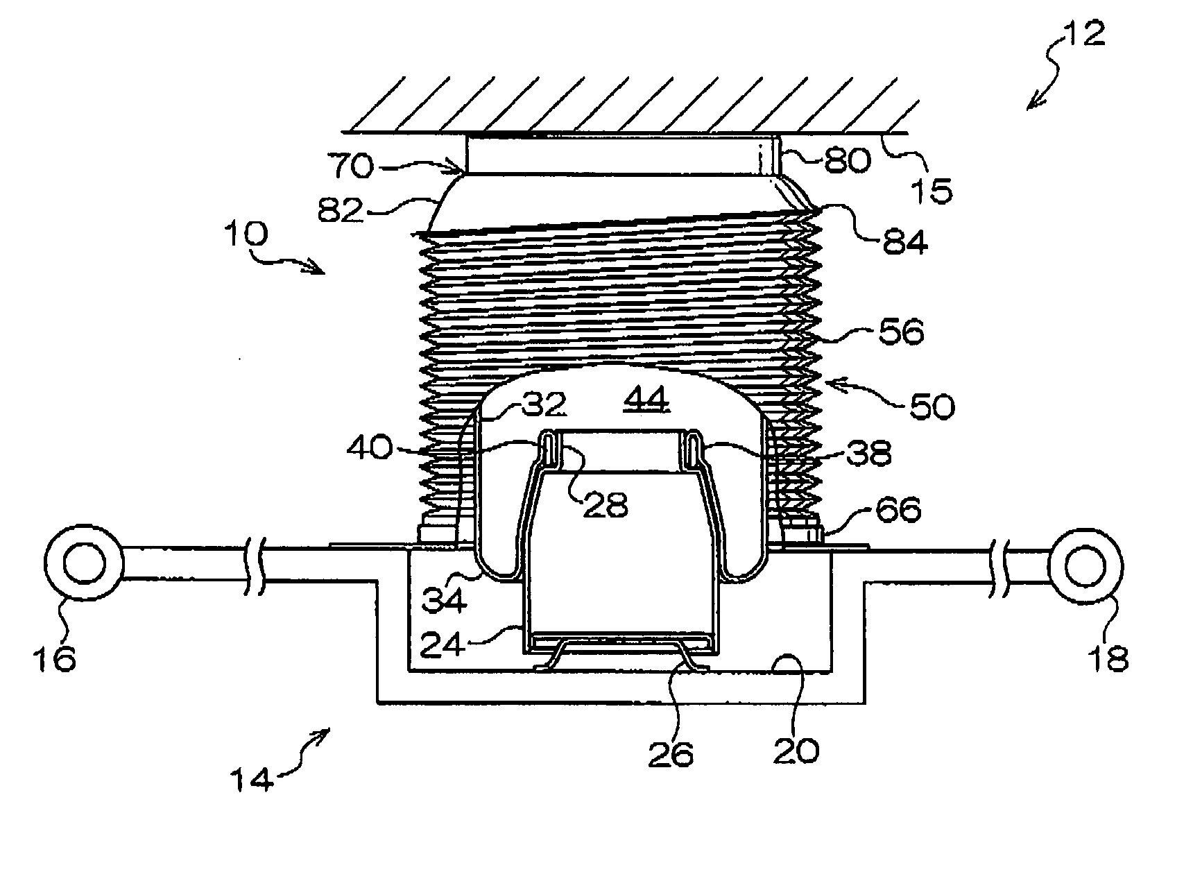
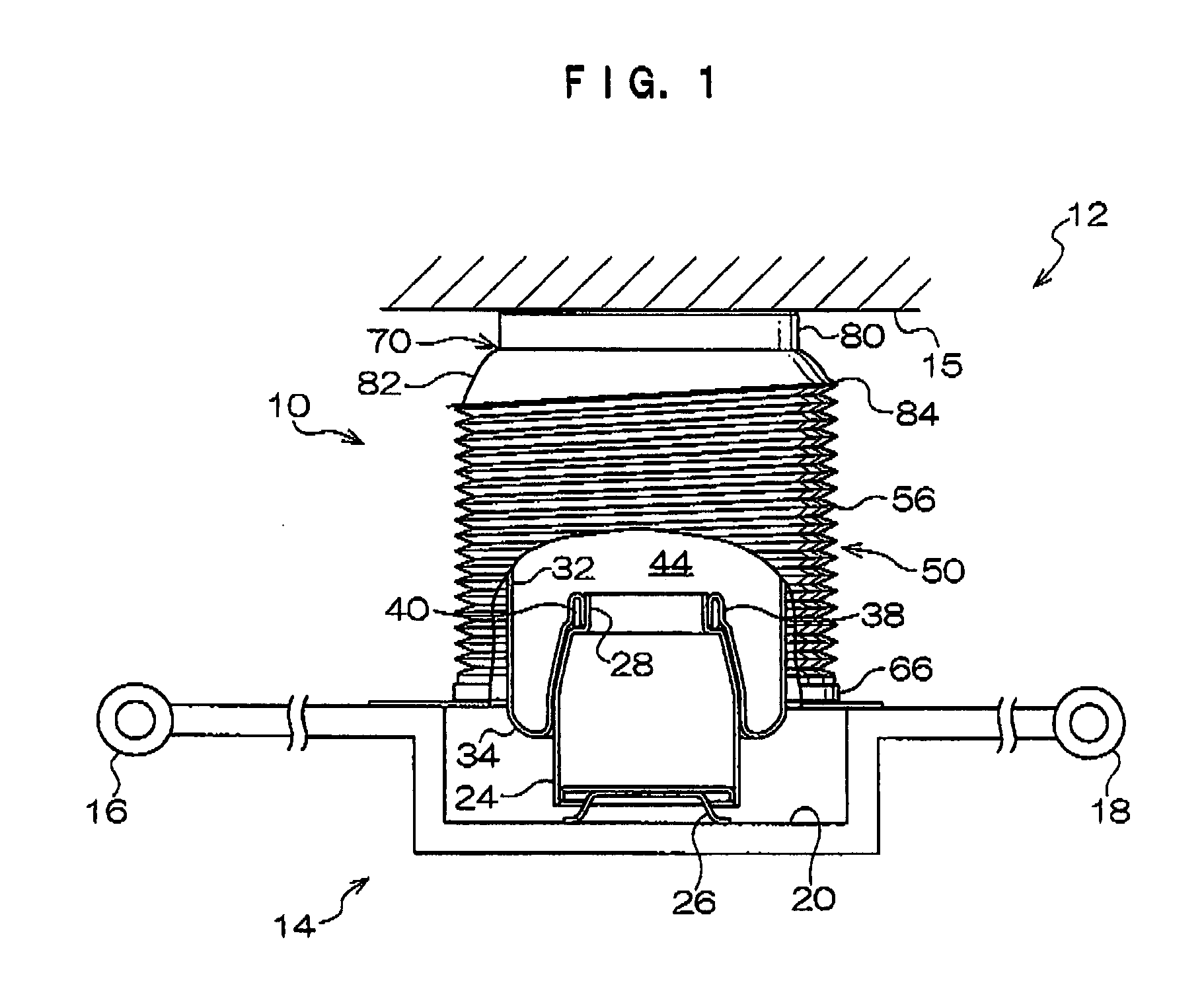
[0043] A typical suspension to which the air spring according to the first embodiment of the present invention has been applied is shown in FIGS. 1-3. As shown in FIG. 1, a suspension 12 is provided with an air spring 10, whose overall form is shaped in a drum form, and a suspension arm 14 formed in a beam-like shape. Cylindrical bushing holders 16, 18 are arranged on the suspension arm 14 respectively at the base end portion and the lead end portion in the longitudinal directions.

[0044] In the suspension arm 14, the bushing holder 16 of the base end side is movably linked at the vehicle body 15 side through a rubber bushing (not shown) and the bushing holder 18 is rotatably linked to a wheel hub (not shown) through a rubber bushing. Due to this, the suspension arm 14 is movably supported by the vehicle body 15 along the up and down directions with the bushing holder 16 at the base end side as the center. Also, a concave holder 20 is formed in the upper surface portion of the suspe...

second exemplary embodiment

[0067] A dustcover in an air spring 90 according to a second embodiment of the present invention is shown in FIG. 4. With the exception of the portion involving a dustcover 92, the air spring 90 according to the second embodiment is essentially the same as the air spring 10 according to the first embodiment. Accordingly, explanations regarding the air spring 90 according to the present embodiment with regard to portions besides the dustcover 92 will be provided with the same symbol number and explanations thereon will be omitted.

[0068] A dustcover 92 formed into a substantially cylindrical shape is provided at the air spring 90 at the outer peripheral side of the diaphragm 32. The dustcover 92 is provided at the upper end portion with a hanger component 94 formed into a substantially capped shape. A linking tube 96 is formed at the upper end side of the hanger component 94 in a substantially cylindrical shape and the top surface side of the linking tube 96 has a top panel 98 that s...


PUM


Abstract

A air spring 10 is provided, where flex deformation of a shoulder portion in a dustcover due to the restorative force of a bellows portion during compression thereof is prevented, whereby deterioration of the life of the dustcover due to such deformation is prevented. With the air spring 10, a stopper 82 of a deformation-preventing cap 70 is arranged at the outer peripheral side of a shoulder portion 54 in a dustcover 50. At the time of compression deformation of a bellows portion 56, the stopper 82 comes into contact with the shoulder portion 54, and flex deformation of the shoulder portion 54 towards a linking tube 52 side is restricted. Due to this, the restorative force from the compression deformed bellows portion 56 via the shoulder portion 54 can be supported by the stopper 82 of the deformation-preventing cap 70. Even in a case where the rigidity of the shoulder portion 54 relative to the restorative force of the compression deformed bellows portion 56 cannot be sufficiently increased, the amount of flex deformation towards the linking tube side of the shoulder portion 54 that received the restorative force of the bellows portion 56 can be decreased.

Description

CROSS-REFERENCE TO RELATED APPLICATION [0001] This application claims priority under 35 USC 119 from Japanese Patent Application No. 2006-037978, the disclosure of which is incorporated by reference herein. BACKGROUND OF THE INVENTION [0002] 1. Field of the Invention [0003] The present invention relates to an air spring that uses pneumatic pressure and which causes the generation of elastic reactive force on an inputted load, and which supports the inputted load with this reactive force, [0004] 2. Description of the Related Art [0005] A device such as that recited in the Official Gazette of JP-A No. 2004-156663 is known as an air spring used in applications such as vehicle suspensions. This air spring is provided with a shell (chamber component) linked to one of a support body or a movable body; a piston (piston component) linked to the other of the support body and the movable body; and a diaphragm that is formed into a cylindrical shape and whose middle portion is in a state where...

Claims


Application Information

Patent Timeline
Patent Type & Authority Applications(United States)
IPC IPC(8): F16F9/04
CPCB60G7/001B60G11/28B60G2200/14F16F9/38B60G2204/126B60G2206/10F16F9/05B60G2202/152
Inventor WATANABE, ISAOYAMAGUCHI, NAOKI
Owner PROSPIRA CORP
Why Eureka
Try Eureka