Method for creating a 3D model of a hydrocarbon reservoir, and method for comparative testing of hydrocarbon recovery techniques

a hydrocarbon reservoir and 3d model technology, applied in the field of 3d model of hydrocarbon reservoirs, can solve the problems of complex and heterogeneous geological and petrophysical characteristics of carbonate reservoirs, inability to completely predict reservoir performance using various recovery techniques, and difficulty in modeling reservoirs via computer software models, etc., to achieve real cost savings, physical testing relatively inexpensively, and the effect of reducing the cost of operation

Active Publication Date: 2015-05-12
HUSKY OIL OPERATIONS
View PDF10 Cites 3 Cited by
  • Summary
  • Abstract
  • Description
  • Claims
  • Application Information

AI Technical Summary

Benefits of technology

[0021]Three dimensional (hereinafter “3D”) representations of detailed components / parts may be “printed” from digital computer files, such as a CAD files describing such part. Such a 3D representation (actual size, or to scale) may be created using a liquid polymer and a high-resolution Digital Light Processor (DLP) projector, whose light emitted therefrom solidifies a liquid photopolymer, resulting in durable plastic part that mimics injection moulding for accuracy, material properties, detail, and surface finish.
[0031]In accordance with a further embodiment of the method of the present invention, printed 3D scaled model of such underground formation, once such 3D model is formed, may then be physically tested relatively inexpensively, as opposed to having to otherwise conduct actual physical tests of the method on the formation itself. The testing of various oil recovery methods on the scaled model of the formation may conducted inexpensively and cheaply, using for example a testing apparatus such as described in U.S. Pat. No. 5,626,191, in order to obtain physical test data to assist in determining the likely success or non-success of a particular method of oil recovery from such a particular formation having those particular characteristics.
[0032]Advantageously, not only is a real cost savings achieved in creating a scaled 3D model in accordance with the method of the present invention by not having to drill, for example SAGD wells in an actual test formation before being able to determine if a SAGD method of recovery is satisfactory for a particular hydrocarbon formation, but a further advantage is achieved in being able to create a plurality of identical 3D models and employ alternate methods of recovery for each of the created identical 3D models, so as to then be able to comparatively select the best manner of oil recovery suited for that particular hydrocarbon formation having those particular physical characteristics. In other words, an optimization process may be carried out, in that a particular method may be chosen after a number of methods have been tried on identical 3D models of the same reservoir, which method accordingly has been optimized and is best suited to provide the quickest and / or greatest oil recovery at the least for acceptable) cost, from the formation.
[0044]As may be seen from the above, the greater the printable resolution of the 3D printer, the smaller the model that may be made, or alternatively the greater the volume of the actual hydrocarbon-containing reservoir that may be realistically modelled from a model of a fixed size.

Problems solved by technology

Disadvantageously, however, computer reservoir modelling software (depending on its sophistication and the amount of formation data which may be input) nonetheless cannot entirely predict reservoir performance using various different recovery techniques.
Particularly in the case of carbonate reservoirs, such reservoirs are often difficult to model via computer software models.
Specifically, carbonate reservoirs have complex and heterogeneous geological and petrophysical characteristics.
They are often naturally fractured, and exhibit complex porosity systems and wetability characteristics, which influence drastically their multi-phase flow properties.
Due to the permanent change invoked on a real-life reservoir once a single oil recovery method is tested thereon, it is impossible to thereafter conduct a further test on such identical formation, using a different method, to determine which method is better.
Such uniqueness and irrevocable changes inflicted on a reservoir when using a particular recovery technique to date has prevented effective comparison of different oil recovery techniques on an individual reservoir on an “apples to apples” basis.

Method used


Image

  • Method for creating a 3D model of a hydrocarbon reservoir, and method for comparative testing of hydrocarbon recovery techniques
  • Method for creating a 3D model of a hydrocarbon reservoir, and method for comparative testing of hydrocarbon recovery techniques
  • Method for creating a 3D model of a hydrocarbon reservoir, and method for comparative testing of hydrocarbon recovery techniques

Examples


Embodiment Construction

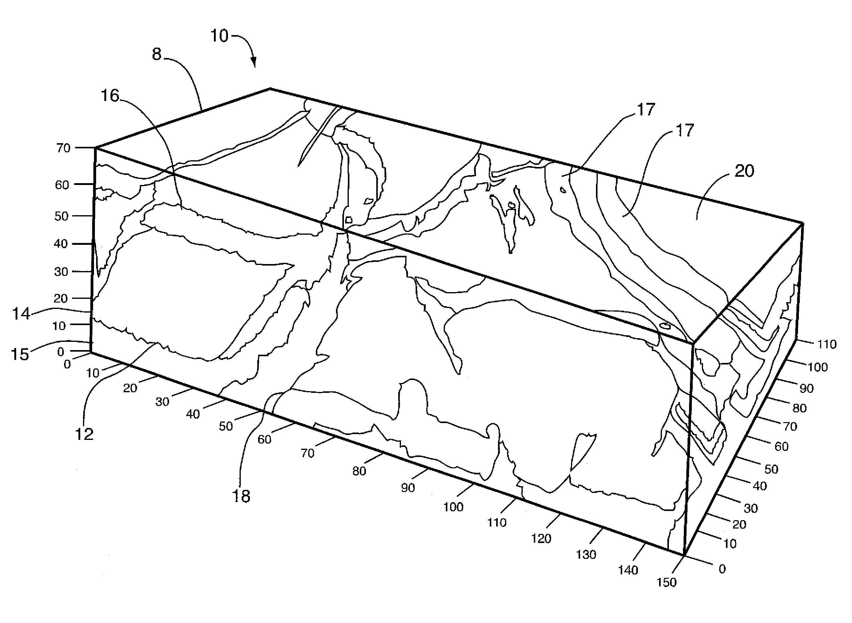
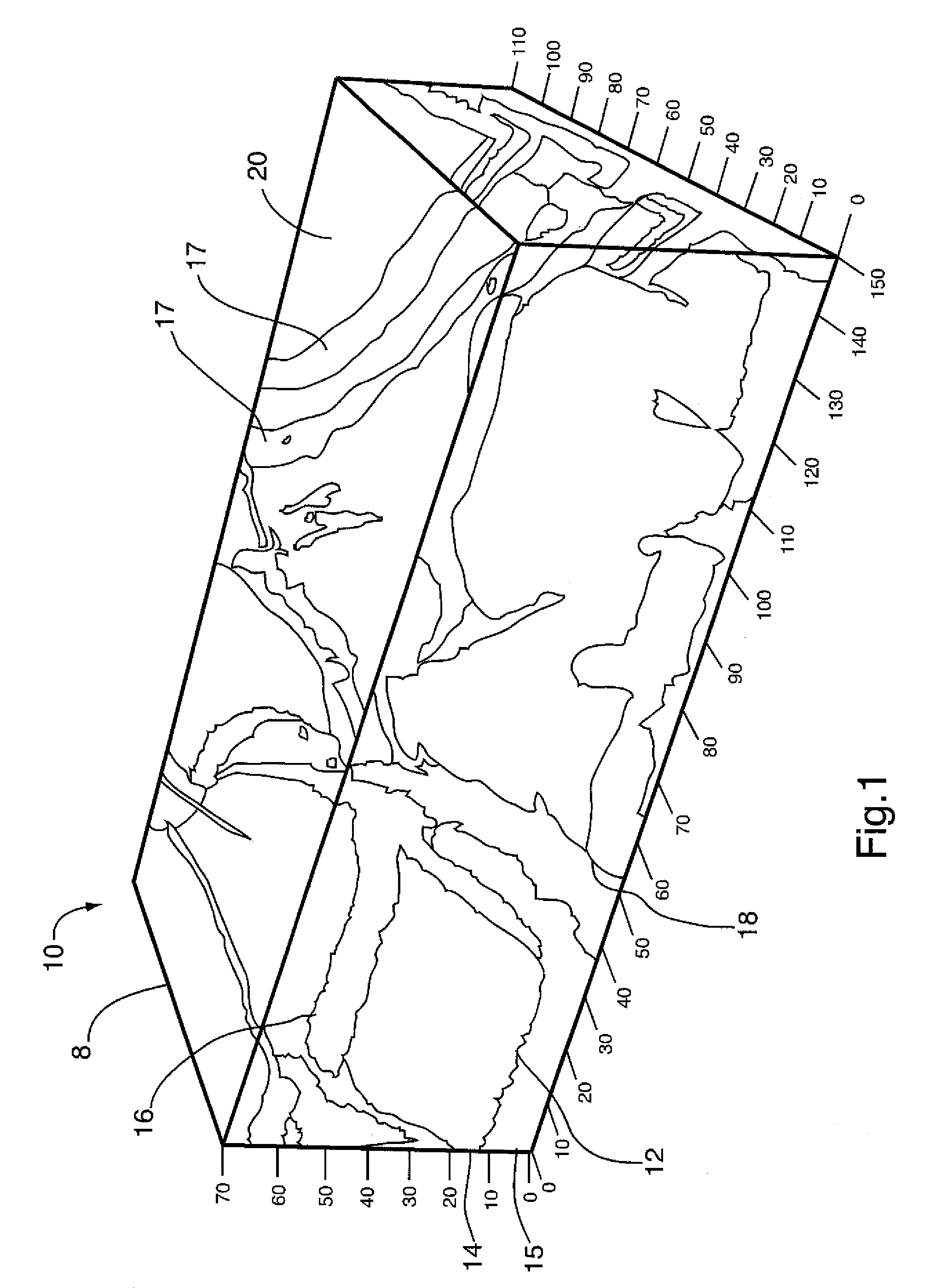
[0071]FIG. 1 shows a 3D perspective view of a portion 8 of an hydrocarbon-containing formation (reservoir) 10, showing a hydrocarbon-containing layer 12 within such formation 10 and various additional carbonate layers 13, 14, 15, 16, which typically are of different composition, density, porosity, permeability and wetability, such different layers 13, 14, 15, 16 in FIG. 1 indicated by different shading.

[0072]While the entire formation may be of an undulating, irregular curvilinear shape, the portion 8 of formation 10 may, for analytic purposes, be of a prismatic shape, which in FIG. 1, for illustrative purposes, is of dimensions 150 m×110 m×70 m (length×width×depth). Such prismatic shape may be chosen for ease of dividing formation 10 into different smaller-sized portions 8.

[0073]As seen from FIG. 1, such formation 10 may possess various fracture fault lines 17, and also may possess various water-containing seams 18.

[0074]Data and information as to various physical characteristics o...


PUM

PropertyMeasurementUnit
thicknessaaaaaaaaaa
thicknessaaaaaaaaaa
pore size volumeaaaaaaaaaa

Abstract

A method of modelling a hydrocarbon-containing reservoir which is representative of such reservoir in at least one physical characteristic such as reservoir porosity or permeability. Data, such as reservoir porosity is firstly determined. Such data is then transformed into printing instructions for a 3D printer. The 3D printer is used to print a reduced-scale model which is representative of the reservoir in respect of the at least one physical characteristic, such as reservoir porosity. A method of comparative testing of different hydrocarbon recovery techniques on a single hydrocarbon-containing reservoir is also disclosed and claimed.

Description

FIELD OF THE INVENTION[0001]The present invention broadly relates to a method for modeling a hydrocarbon reservoir, and more particularly to a method for creating a physical three dimensional model of a hydrocarbon-containing reservoir having one or more physical characteristics of the formation.BACKGROUND OF THE INVENTION[0002]Various techniques currently exist for recovery of viscous oil from underground deposits, including recovery of oil from within oil sand and oil carbonate formations which may have a “pay” zone in the range of between 15 m to 200 m thickness, typically commencing 20-500 m beneath the surface.[0003]One such recovery technique is the so-called SAGD technique (“Steam Assisted Gravity Drainage”), such as disclosed in U.S. Pat. No. 5,273,111 to Brannan et al, 1993), which uses an upper and lower pair of vertically-aligned horizontal wells drilled into a “pay” zone. Heated steam is injected into the upper well of such pair of horizontal wells, and thereby into the ...

Claims


Application Information

Patent Timeline
Patent Type & Authority Patents(United States)
IPC IPC(8): G06G7/48B29C67/00E21B43/00
CPCE21B43/00B29C67/0059B33Y50/00B33Y80/00B29C64/112
Inventor FREDERICK, LAWRENCE
Owner HUSKY OIL OPERATIONS
Why Eureka
Try Eureka