
Method and apparatus for defect detection

a defect detection and defect technology, applied in the field of defect detection, can solve the problems of uneconomic use of such methods in continuous or batch processing of low-cost high-volume articles, inconvenient cost, and doubt of the appropriateness of this approach

Inactive Publication Date: 2011-12-01
TGT ENTERPRISE LTD
View PDF4 Cites 4 Cited by
  • Summary
  • Abstract
  • Description
  • Claims
  • Application Information

AI Technical Summary

Benefits of technology

"The invention provides a system and method for detecting defects in membranous articles, such as gloves, using an emitter probe and a sensor. The system measures the potential difference between the probe and sensor and detects defects based on the measurement. This allows for efficient detection of defects during production or reconditioning of gloves, without damaging them. The system is particularly useful for examination or surgical gloves, and can support economical testing of these gloves in line manufacturing or during reprocessing."

Problems solved by technology

In each case, these methods have the inconvenience of cost, residence time and other issues that make the use of such methods uneconomic for continuous or batch type processes for low cost high volume articles.
Whilst a statistical approach is well established, there remains some doubt of the appropriateness of this approach given that an aberrant result for a non tested glove may have severe consequences if a defect were to leave too and infected health worker.
If there are holes, then small drops of water will leak through the material and, as a result, the glove will be considered to have a defect such as a pin hole.
The method is slow, and not very suitable for high volume batch processing, as it takes a few seconds to fill the glove (about 10 seconds, so the glove won't be broken by the water jet), more time for the glove to leak, another few seconds to empty the glove and so on.
In the end, after about a minute, the decision can be made but it will result also in a wet glove.
Besides the large amount of time it takes for the decision to be made, it is close to impossible to automate the whole process.
This test is usually a statistical one and the error margins are somewhat large.

Method used


Image

  • Method and apparatus for defect detection
  • Method and apparatus for defect detection
  • Method and apparatus for defect detection

Examples


Embodiment Construction

[0028]The invention is directed to a method and system based on the usage of high voltage which produces an intense electric field around a membranous article, for the purpose of detecting electrical charge leakages of the membranous article.

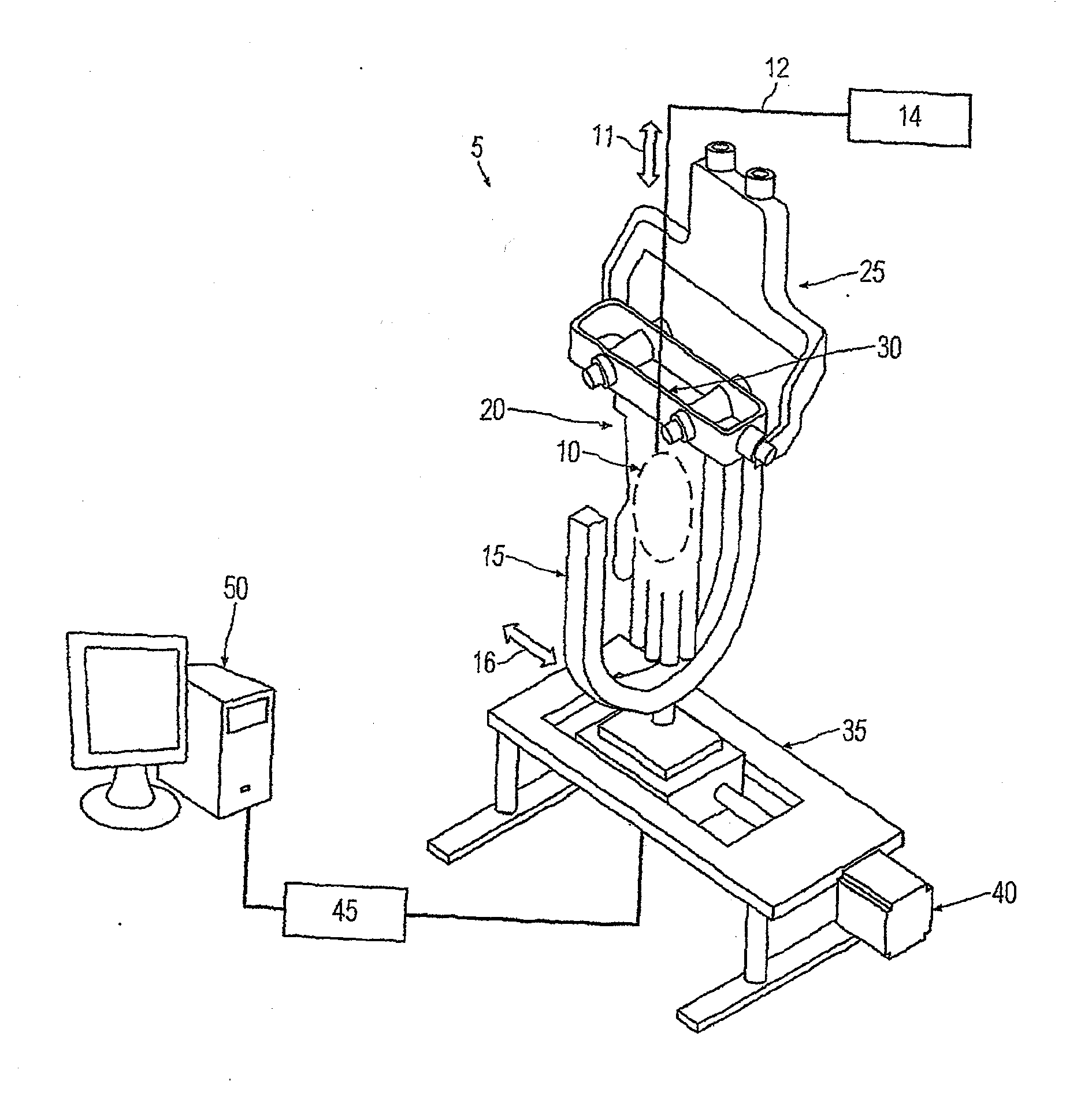
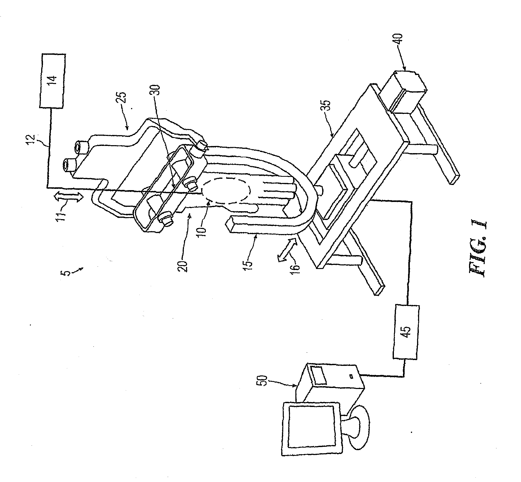
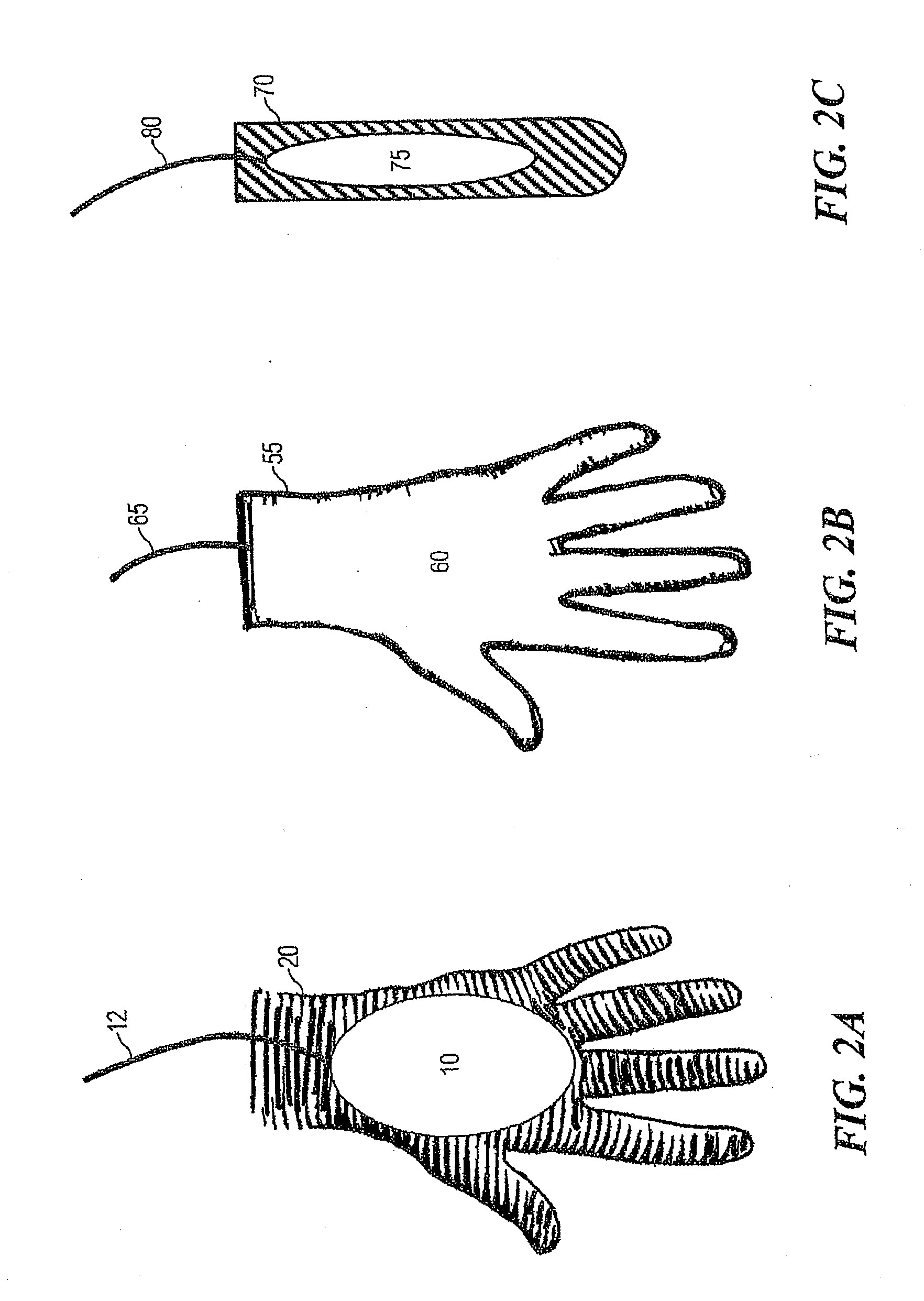
[0029]FIG. 1 shows a schematic view of one embodiment of the present invention. Here a High Voltage generator 14 is supplying high electric potential to an emitter probe 10 via a cable 12 which by a conveyor (not shown) an up / down motion 11 is introduced inside the glove to be tested. The glove carrier 30 brings the glove 20 in to be tested position. Then, the emitter probe 10 is placed by the conveyor down into position. Next the U-shape sensor 15 commences a horizontal movement 16 to scan the entire surface of the glove 20 by a Sensor Horizontal Slider 35. Said slider 35 is operated by a motor 40, which may be under manual or automated control.

[0030]During the scan an Analog-Digital Converter 45 converts the electric potential difference (Volt...


PUM

PropertyMeasurementUnit
timeaaaaaaaaaa
frequenciesaaaaaaaaaa
diameteraaaaaaaaaa

Abstract

A system for detecting a defect in a membranous article (20) comprising: an emitter probe (10) connected to an electrical supply (14), said probe (10) insertable into a cavity of said article (20); a sensor (15) for receiving an electrical discharge from said probe (10); a conveyor system for bringing the probe and sensor into mutual proximity; a processor for measuring the potential difference between the probe and sensor, said processor capable of detecting a defect based upon said measurement.

Description

FIELD OF THE INVENTION[0001]The invention relates to the detection of defects including tears and pinholes, and in particular such defects in membranous articles, such as gloves used for medical purposes and condoms.BACKGROUND OF THE INVENTION[0002]Membranous articles are typically made from latex, synthetic rubber, or other visco-elastic polymer. Such membranous articles include surgical gloves or other gloves used for medical purposes, and condoms. Such gloves provide barrier protection for healthcare professionals against micro-organisms and blood borne viruses including hepatitis B. They also provide barrier protection against chemicals that are routinely used in medical procedures. As a consequence, the routine wearing of gloves are an essential requirement for operator and patient safety.[0003]Glove manufacturers assess gloves for pre-existing pinhole defects using the European Standard EN 455-125 or the ASTM standards. These documents state that the water tightness test, in w...

Claims


Application Information

Patent Timeline
Patent Type & Authority Applications(United States)
IPC IPC(8): G01N27/20
CPCA61B19/041G01M3/40A61F6/065A61F6/04A61B42/30G01N27/20
Inventor BODEA, DANIEL-CONSTANTINHAMPE, PATRICK
Owner TGT ENTERPRISE LTD
Learn More