Spatial derivative-based ray tracing for volume rendering

a volume rendering and derivative technology, applied in the field of medical imaging, can solve the problems of limited 3d visualization, and limited applicability of orbit and zoom approach for rendering and viewing volume medical datasets

Inactive Publication Date: 2015-05-19
AUTHENTIC
View PDF4 Cites 4 Cited by
  • Summary
  • Abstract
  • Description
  • Claims
  • Application Information

AI Technical Summary

Benefits of technology

[0009]Spatial derivative based ray tracing is a useful method of visualizing volume data because it requires no user interaction to reveal the

Problems solved by technology

These techniques generate a set of individual 2D images that can be displayed in a 3D visualization as a “volume dataset.” Typically, however, the extent of the 3D visualization is limited to “orbiting” and “zooming.” In an “orbit” mode, the view of the object being rendered is like an orbiting satellite in that the viewer can move around the object being view

Method used


Image

  • Spatial derivative-based ray tracing for volume rendering
  • Spatial derivative-based ray tracing for volume rendering
  • Spatial derivative-based ray tracing for volume rendering

Examples


Embodiment Construction

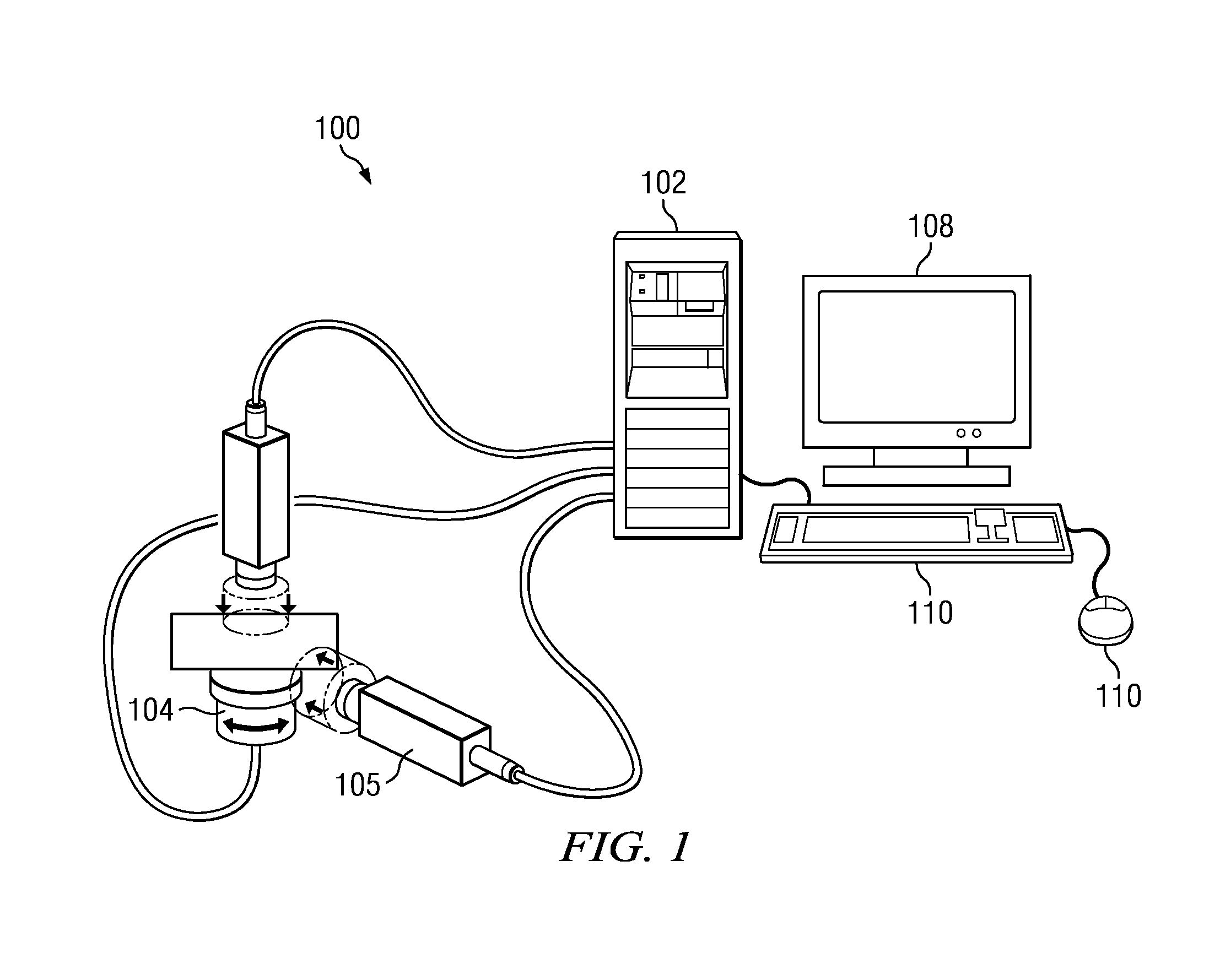
[0022]As illustrated in FIG. 1, a system 100 in which the subject matter herein is implemented comprises a computer system 102 having a display monitor 108, and one or more input devices 110 such as a keyboard, a pointing device, or the lie. The computer system 102 is illustrated as a desktop workstation, but this is not a limitation, as the system may be implemented in a laptop or notebook computer, a wireless computing device (such as an iPad), or any other computing machine that includes a display. The techniques of this disclosure are not limited to any particular type of computing device, system or architecture, and one or more of the elements of the machine may be located in different locations. Thus, for example, the display monitor may be positioned remotely from other components. For convenience of illustration only, the computer system 102 is shown as receiving inputs from a pair of imaging devices 106 that are associated with a support 104. The support 104 rotates or reci...


PUM


Abstract

A machine-implemented display method that, with respect to a volume dataset being rendered, enables a user to navigate to any position in space and look in any direction. Preferably, the volume dataset is derived from a computer tomography (CT) or magnetic resonance imaging (MRI) scan. With the described approach, the user can see details within the dataset that are not available using conventional visualization approaches. The freedom-of-motion capability allows the user to go to places (positions) within the volume rendering that are not otherwise possible using conventional “orbit” and “zoom” display techniques. Thus, for example, using the described approach, the display image enables a user to travel inside physical structures (e.g., a patient's heart, brain, arteries, and the like).

Description

[0001]This application is based on and claims priority to Ser. No. 61 / 559,928, filed Nov. 15, 2011.BACKGROUND OF THE INVENTION[0002]1. Technical Field[0003]This disclosure relates generally to medical imaging.[0004]2. Background of the Related Art[0005]Medical imaging is the technique used to create images of the human body or parts thereof for clinical purposes (medical procedures that seek to reveal, to diagnose or to examine disease) or medical science (including the study of normal anatomy and physiology). Computer tomography (CT) and magnetic resonance imaging (MRI) are two of the most common approaches. These techniques generate a set of individual 2D images that can be displayed in a 3D visualization as a “volume dataset.” Typically, however, the extent of the 3D visualization is limited to “orbiting” and “zooming.” In an “orbit” mode, the view of the object being rendered is like an orbiting satellite in that the viewer can move around the object being viewed from any angle ...

Claims


Application Information

Patent Timeline
IPC IPC(8): G06T15/06A61B6/00
CPCG06T15/06G06T15/08
Inventor MCKENZIE, LEE R.MCKENZIE, MARK C.
Owner AUTHENTIC
Why Eureka
Try Eureka