X-ray photography apparatus

a technology of x-ray and photography, which is applied in the direction of radiation diagnostic diaphragms, patient positioning for diagnostics, applications, etc., can solve the problems of large burden on patients, limited diagnostic information on parts of teeth or gums,

Active Publication Date: 2015-05-19
MORITA MFG CO LTD
View PDF15 Cites 16 Cited by
  • Summary
  • Abstract
  • Description
  • Claims
  • Application Information

AI Technical Summary

Benefits of technology

[0016]The tomographic image similar to the conventional intraoral radiography (the dental radiography) can be generated by superposing the plural projection images. In the tomographic image, because metallic artifact is not generated, the image diagnosis of the target place can properly be made. The tomographic image having an excellent contrast can be acquired by the filtered back projection. Therefore, the target place can be clearly observed to make the image diagnosis. Since the tomographic image generated by the method of stacking and the tomographic image generated by the filtered back projection are both generated, the image diagnosis can be properly made while shortcomings of both of the tomographic images are compensated.
[0048]The pseudo intraoral radiography region can easily be designated through the panoramic image such that the photographing target object is included in the pseudo intraoral radiography region.
[0051]Therefore, an object of the present invention is to provide a technology for enabling more diagnostic information on part of the row of teeth or the gum from the identical frame data.

Problems solved by technology

However, it is necessary to dispose in advance the X-ray detection means in the mouth cavity of the patient, and thus a large burden is placed on the patient.
Therefore, in the conventional X-ray photography apparatus, only one type tomographic image is generated for a specific tomographic plane, and diagnostic information on part of the row of teeth or the gum is limited.

Method used


Image

  • X-ray photography apparatus
  • X-ray photography apparatus
  • X-ray photography apparatus

Examples


Embodiment Construction

[0077]Hereinafter, preferred embodiments of the present invention will be described with reference to the accompanying drawings. In the drawings, for the sake convenience, occasionally, the size or the number of pieces of each component is indicated while magnified or simplified as occasion demands.

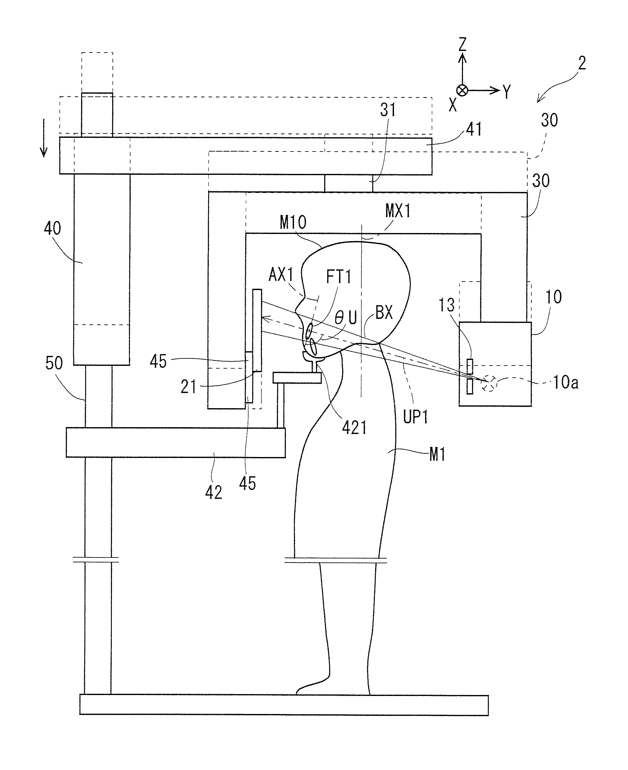
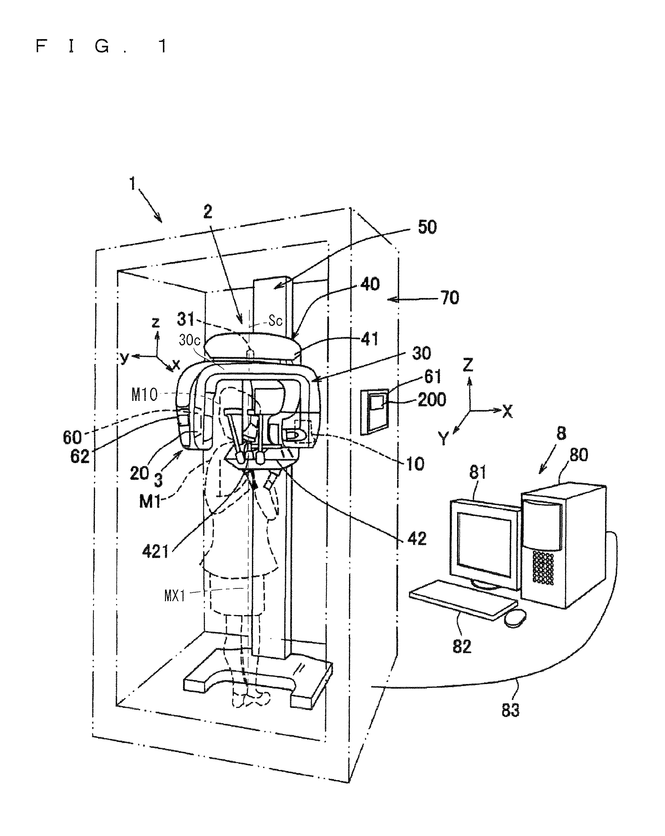
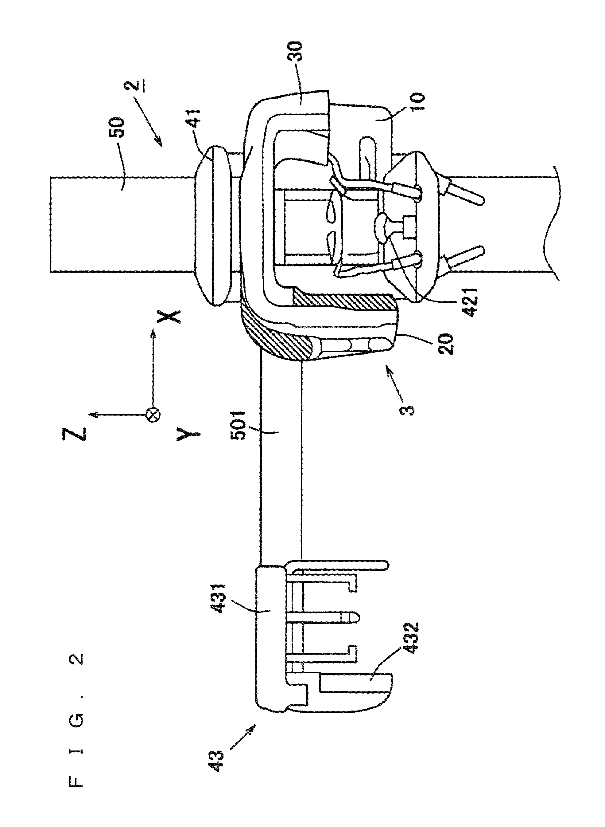
[0078]FIG. 1 is a schematic perspective view of an X-ray photography apparatus 1 according to a preferred embodiment of the present invention. FIG. 2 is a partial front view of the X-ray photography apparatus 1 on which a cephalostat 43 is mounted. FIG. 3 is a block diagram of the configuration of the X-ray photography apparatus 1.

[0079]The X-ray photography apparatus 1 is substantially comprised of manipulation display parts 61 and 62, a main body 2, and an image processing device 8. The manipulation display parts 61 and 62 act as display element while setting a photographic region CA. The main body 2 collects X-ray projection data (frame data) by performing X-ray photography to the phot...


PUM


Abstract

An X-ray photography apparatus including: a turning arm that supports an X-ray generator and an X-ray detector while the X-ray generator and the X-ray detector are opposed to each other so that a head of a patient can be interposed therebetween; and a moving mechanism that turns the turning arm about a turning axis with respect to the head and moves the turning arm in a direction perpendicular to the turning axis with respect to the head. The X-ray photography apparatus further includes: an image processor that generates an X-ray image based on an electric signal output from the X-ray detector; and a photographic region designation receiving part that designates part of a row of teeth along a dental arch as a pseudo intraoral radiography region. The image processor generates plural tomographic images by applying convolution and filtered back projection to X-ray image data obtained by pseudo intraoral radiography.

Description

BACKGROUND OF THE INVENTION[0001]1. Field of the Invention[0002]The present invention relates to an X-ray photography apparatus.[0003]2. Description of the Background Art[0004]Conventionally what is called intraoral radiography (dental radiography), in which X-ray a detection means (such as an X-ray film and an X-ray sensor panel) is set in the mouth cavity of a patient to photograph part of a row of teeth or a gum, is performed in X-ray photography of the dental field. Because only a local region is irradiated with an X-ray in the intraoral radiography, advantageously the photographing is simply performed and X-ray exposure is reduced. However, it is necessary to dispose in advance the X-ray detection means in the mouth cavity of the patient, and thus a large burden is placed on the patient.[0005]Therefore, Japanese Patent Application Laid-Open No. 2007-136163 has made a proposal that panoramic photography is performed using a panoramic image photographing device and a tomographic ...

Claims


Application Information

Patent Timeline
Patent Type & Authority Patents(United States)
IPC IPC(8): A61B6/14A61B6/00A61B6/02A61B6/03A61B6/04A61B6/06
CPCA61B6/145A61B6/032A61B6/025A61B6/035A61B6/06A61B6/14A61B6/4476A61B6/469A61B6/5223A61B6/545A61B6/0457A61B6/0478A61B6/0487
Inventor SADAKANE, TOMOYUKIYOSHIKAWA, HIDEKI
Owner MORITA MFG CO LTD
Why Eureka
Try Eureka