
Propulsion system for a self-propelled vehicle with multiple electric drive units

a technology of electric drive unit and self-propelled vehicle, which is applied in the direction of electric propulsion mounting, electric devices, cycles, etc., can solve the problems of difficult practical application of such ideas, difficult to overcome implementation problems, and mechanical limits that cannot be exceeded to achieve the maximum power of electric motors, etc., to increase the autonomy of the vehicle, increase the efficiency of the vehicle, and increase the effect of performance or efficiency

Active Publication Date: 2015-05-26
SOLAREDGE TECH LTD
View PDF11 Cites 7 Cited by
  • Summary
  • Abstract
  • Description
  • Claims
  • Application Information

AI Technical Summary

Benefits of technology

[0012]A second advantage of the invention is the fact that, having two or more o coupled with the same clutch ring gear, it is possible to increase the autonomy of the vehicle, since the performance of the motors can be modulated individually, so that it even possible to temporarily stop one (or several) of them operating so as to obtain economical performance.
[0013]A third advantage of the invention is the fact that, having two or more motors coupled with the same clutch ring gear, it is possible to use software to manage the temperature of the individual motors, sending greater quantities of current to the motor with the lowest temperature, then inverting the function when the condition between the various motors changes.
[0014]Having an overrunning (or freewheel) coupling between the friction clutch coupling and the driving shaft of the motor or motors means that it is possible to also have the further advantage of preventing the slowest motor from braking the fastest motor and / or being able to use different gear ratios to increase performance or efficiency, or to increase the acceleration or top speed, of the vehicle.
[0015]Adopting two separate operating and control systems for each motor gives the further advantage of being able to have a safety backup unit in the event of a fault in one of the motors or one of the electronic control units.

Problems solved by technology

In propulsion systems for self-propelled vehicles in which a mechanical transmission, which sends power to the driving wheels of the vehicle and receives at input the power supplied by an electric motor by means of a clutch coupling and a gearbox with a moderate number of gears, the continual search for construction solutions able to develop increasingly high propulsive powers, with drive units that at the same time are compact, clashes with implementation problems which are quite difficult to overcome.
However, the practical application of such ideas is not entirely easy.
But since said speed cannot be increased indefinitely, it quickly becomes apparent that the maximum power that the electric motor can supply is subject to mechanical limits which cannot be surpassed.

Method used


Image

  • Propulsion system for a self-propelled vehicle with multiple electric drive units
  • Propulsion system for a self-propelled vehicle with multiple electric drive units
  • Propulsion system for a self-propelled vehicle with multiple electric drive units

Examples


Embodiment Construction

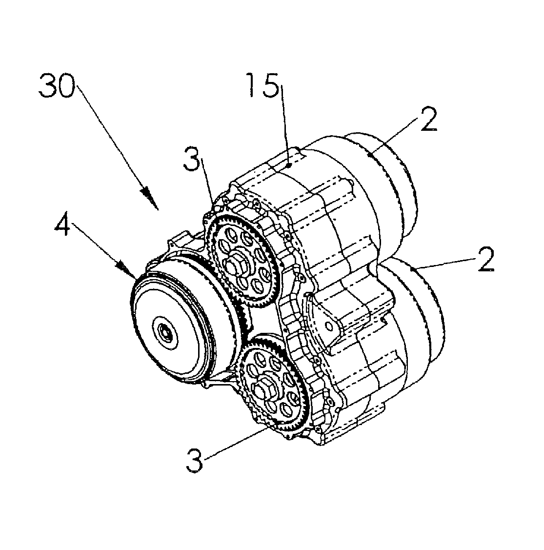
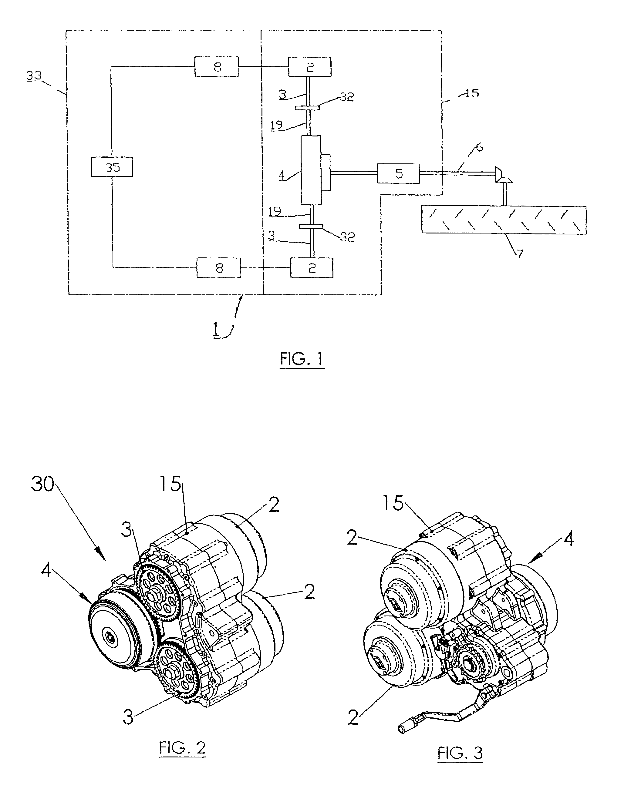
[0022]With reference to the accompanying drawings, FIG. 1 schematically illustrates in its entirety a propulsion system for a self-propelled vehicle which basically comprises a drive unit 33, 15 which—powered by electric batteries (not illustrated)—generates mechanical power at output; and a mechanical transmission 6 which receives at input the power generated by the drive unit 33, 15 and conveys it at output to one or more driving wheels 7 for generating the advancing motion of the vehicle relative to the ground.

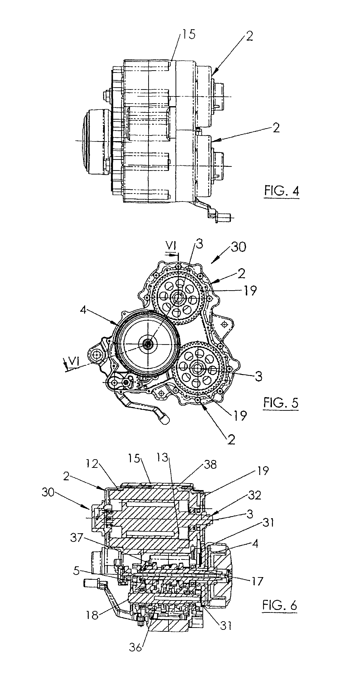
[0023]The drive unit 33, 15—particularly advantageous for use for example on a motorcycle, without thereby limiting the scope of the invention—comprises in particular a motor body 15 which—positioned upstream of the mechanical transmission 6 [FIG. 1]—integrates and contains in a single body [FIGS. 2 to 5]:[0024]electric propulsion means 30;[0025]a friction clutch coupling 4 operatively positioned downstream of and mechanically connected to the electric propulsion means 30; ...


PUM


Abstract

A propulsion system for a self-propelled vehicle comprises a motor body which is associated with a mechanical transmission conveying motion to the driving wheels of the vehicle, and which integrates and contains in a single body electric propulsion means, comprising at least several components of a brushless rotary motor; a clutch coupling located downstream of and mechanically connected to the electric propulsion means; and a gearbox with discontinuous gear ratios, having an input shaft connected to the clutch coupling and an output shaft coming out to the outside of the motor body and connecting to the mechanical transmission. The electric propulsion means comprise the components of at least two brushless motors, each equipped with a respective driving shaft provided with a pinion which is coupled by meshing with a predetermined ratio to a clutch coupling.

Description

[0001]This application is the National Phase of International Application PCT / IT2012 / 000095 filed Mar. 28, 2012 which designated the U.S.[0002]This application claims priority to Italian Patent Application No. RN2011A000036 filed May 18, 2011, which application is incorporated by reference herein.TECHNICAL FIELD[0003]This invention relates to a propulsion system for self-propelled vehicle with multiple electric drive units.BACKGROUND ART[0004]In propulsion systems for self-propelled vehicles in which a mechanical transmission, which sends power to the driving wheels of the vehicle and receives at input the power supplied by an electric motor by means of a clutch coupling and a gearbox with a moderate number of gears, the continual search for construction solutions able to develop increasingly high propulsive powers, with drive units that at the same time are compact, clashes with implementation problems which are quite difficult to overcome.[0005]In fact, it is known in general that...

Claims


Application Information

Patent Timeline
Patent Type & Authority Patents(United States)
IPC IPC(8): B60K1/02
CPCB60K1/02Y10T74/19056B60Y2200/12B60L2220/42B60L2220/46Y02T10/64
Inventor MAZZINI, SAMUELE
Owner SOLAREDGE TECH LTD
Learn More