Non-chattering ball detent torque limiter

a torque limiter and ball detent technology, applied in the direction of couplings, slip couplings, couplings, etc., can solve the problems of expensive overhaul process, inability to include “soft” mechanical cushioned stops, and inability to adjust the torque, etc., to achieve the effect of easy resetability

Inactive Publication Date: 2015-05-26
MOOG INC
View PDF11 Cites 1 Cited by
  • Summary
  • Abstract
  • Description
  • Claims
  • Application Information

AI Technical Summary

Benefits of technology

[0005]The present invention solves the damage and noise problems associated with a breakout event experienced by a conventional torque-limiting assembly. Moreover, the present invention provides a torque-limiting assembly that is easily reset for continued operation after a breakout event.
[0006]The present invention provides a ball-detent torque-limiting assembly with breakout means for maintaining an axial separation distance between opposing pocketed surfaces of the assembly once the primary balls of the assembly have rolled out of their pockets as a result of relative rotation between the opposing pocketed surfaces when a torque limit of the assembly is exceeded. The axial separation distance maintained by the breakout means is at least as great as the diameter of the primary balls, and may be greater than the diameter of the primary balls. The breakout means may assume the axially directed spring load that urges the opposing pocketed surfaces together, thereby preventing the primary balls from entering and exiting the pockets in quick and violent succession following breakout and avoiding damage to the torque-limiting assembly.
[0008]The torque limiting assembly of present invention protects surface and internal components of an EMA, and is easily resettable. The present invention finds application in both unidirectional and bidirectional torque transmission systems.

Problems solved by technology

However, conditions may arise where an errant command results in the EMA being driven beyond the normal electrical stroke endpoint into a mechanical stroke endpoint.
Because of usual space constraints in aircraft, extra room to include “soft” mechanically cushioned stops is not available.
If an EMA is driven at sufficient rate into a mechanical end stop either during an in-flight event or as a result of a rigging error during assembly, significant damage usually occurs.
A costly overhaul process is required to replace parts and return the unit to service.
With the high spring force and the abrupt shape of the pockets, the continued motion of the balls rolling into and out of pockets results in a very violent series of events.
The balls experience very high and repeated impact loading and may fracture.
Also, the edges of the pockets in the plates may generate harmful debris.
Tests have shown significant damage to ball pockets after several encounters.

Method used


Image

  • Non-chattering ball detent torque limiter
  • Non-chattering ball detent torque limiter
  • Non-chattering ball detent torque limiter

Examples


Embodiment Construction

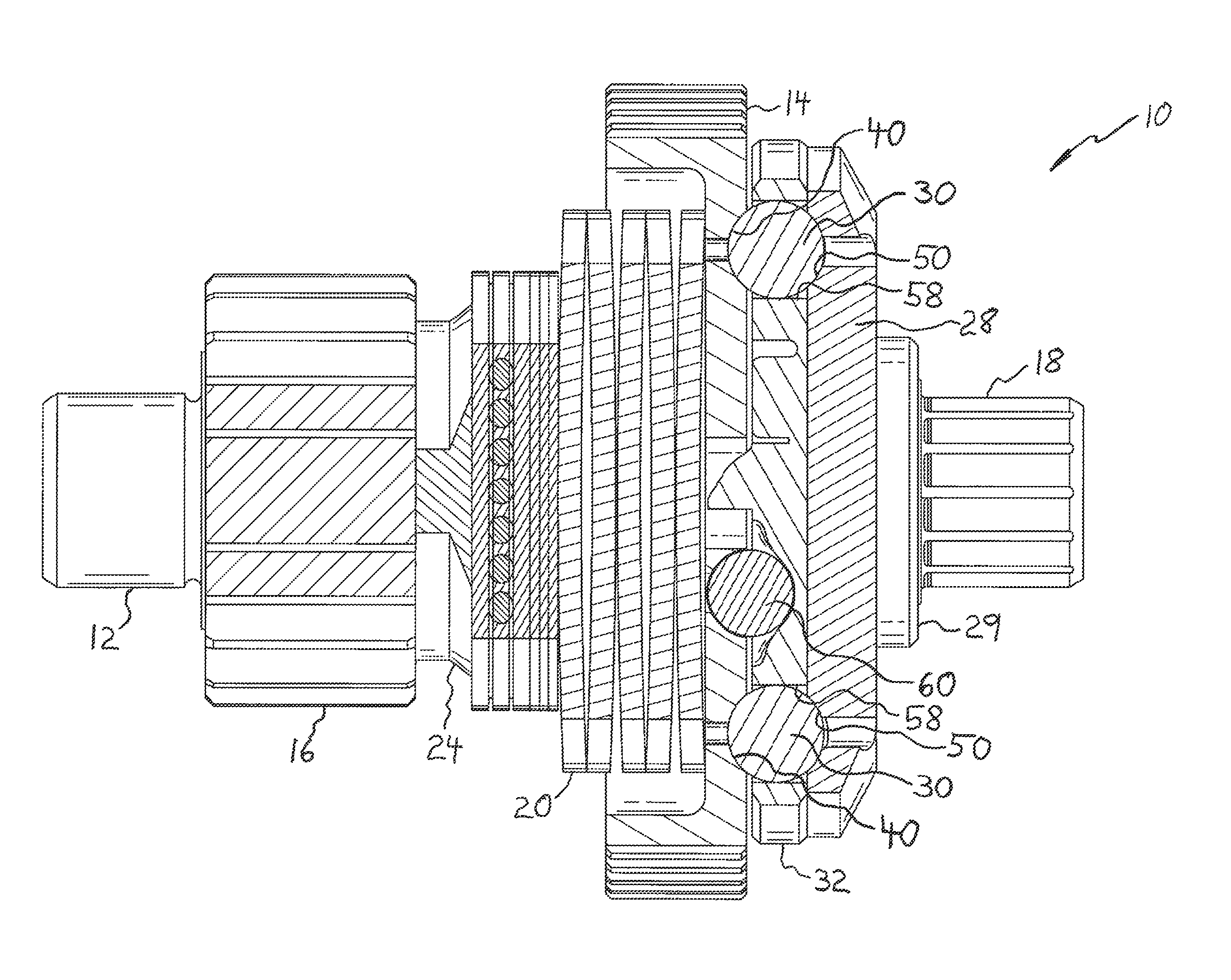
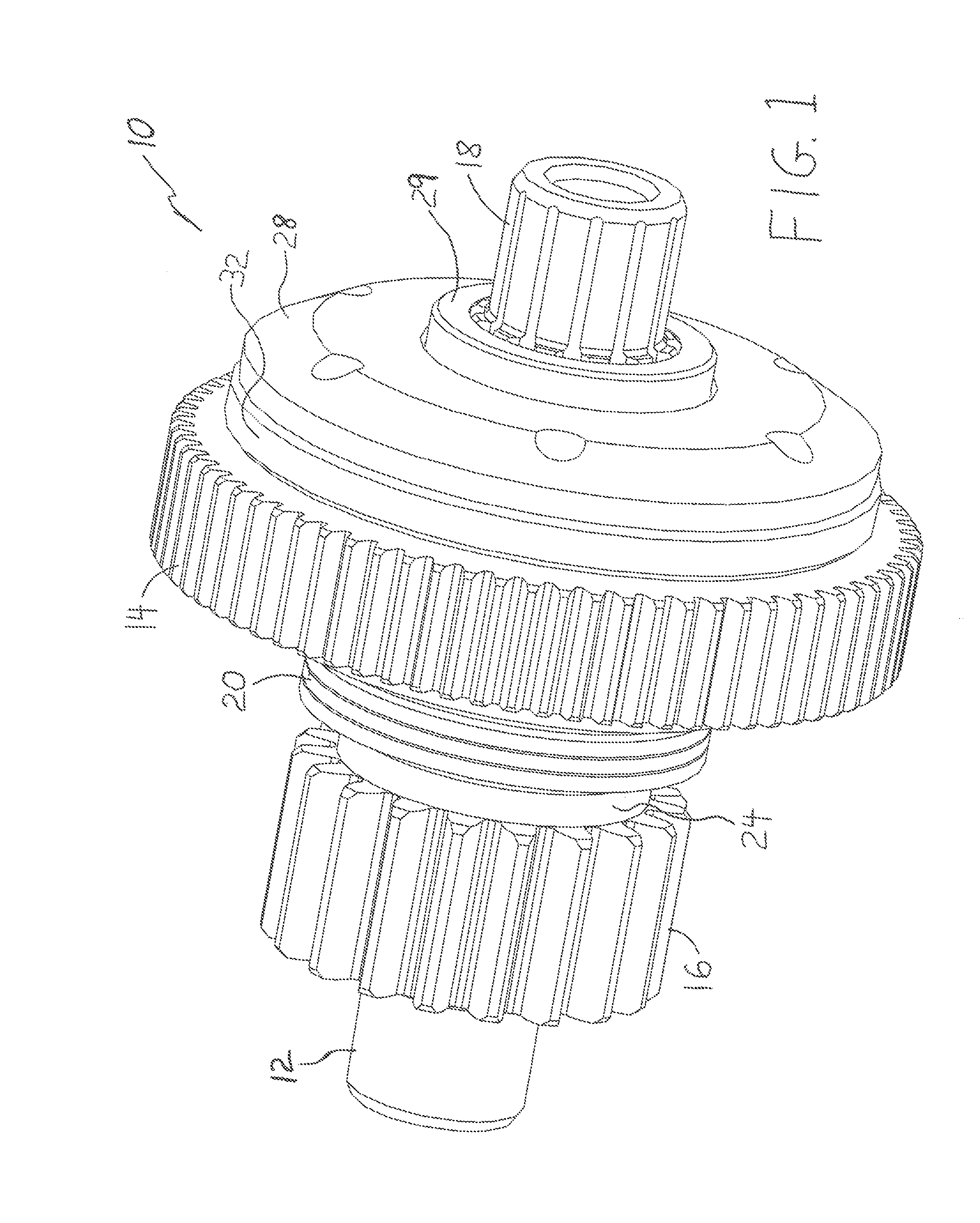
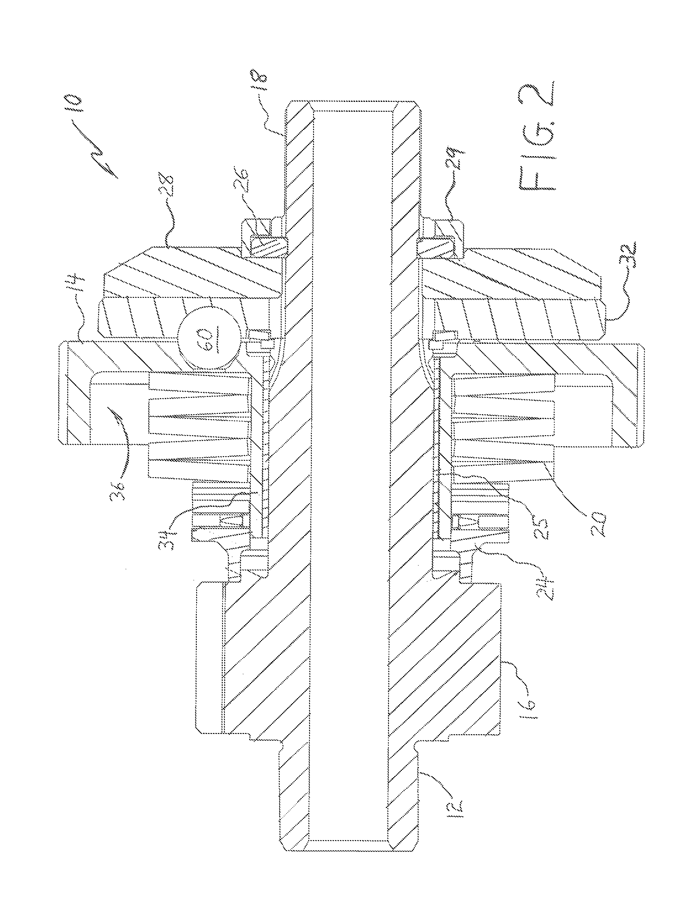
[0024]FIGS. 1-4 depict a bidirectional torque-limiting assembly 10 formed in accordance with an embodiment of the present invention. Assembly 10 has utility in an EMA drive system for actuating an aircraft control surface, e.g. a spoiler panel, flap, slat, horizontal stabilizer, or other aircraft control surface.

[0025]Assembly 10 generally comprises an elongated shaft 12 supporting an input gear 14 and an output gear 16. Shaft 12 includes a splined end 18 provided with a circumferential retaining groove 19. Assembly 10 also comprises a spring 20, washers 22, a roller bearing 23, a collar 24, and retainer clips 26 all mounted on shaft 12. Assembly 10 further comprises a backing plate 28 mounted on shaft 12 and a cap 29 covering retainer clips 26.

[0026]Output gear 16 is mounted on shaft 12 for rotation with the shaft. In the context of the present specification, “mounted on” is meant in a broad sense to include a part that is separately manufactured and slid onto shaft 12, as well as ...


PUM


Abstract

A ball-detent torque-limiting assembly has breakout means for maintaining an axial separation distance between opposing pocketed surfaces of the assembly once the primary balls of the assembly have rolled out of their pockets, wherein the axial separation distance maintained by the breakout means is at least as great as the diameter of the balls. The breakout means may include a plurality of secondary balls deployed in a breakout event. The breakout means assumes the axially directed spring load that urges the opposing pocketed surfaces together, thereby preventing the primary balls from entering and exiting the pockets in quick and violent succession following breakout and avoiding damage to the torque-limiting assembly. The torque-limiting assembly is resettable by counter-rotation following a breakout event.

Description

FIELD OF THE INVENTION[0001]The present invention relates generally to electromechanical actuation of aircraft control surfaces, and more particularly to torque limiters designed to prevent transmission of excessive torque and load after an electromechanical actuator for moving an aircraft control surface has encountered a hard mechanical stop.BACKGROUND OF THE INVENTION[0002]Aircraft control surfaces, for example flaps located on the trailing edge of a fixed wing, slats located on a leading edge of a fixed wing, spoiler panels, aileron surfaces, and the like, have traditionally been actuated by hydraulic actuation systems. More recently, electromechanical actuators (“EMAs”) have gained acceptance in the aviation industry for adjusting the position of control surfaces. EMAs are designed to sweep through a given stroke, linear or rotary, but must have definite points where the stroke must start and end. In practice, two sets of endpoints are defined: one set defines the electrical st...

Claims


Application Information

Patent Timeline
Patent Type & Authority Patents(United States)
IPC IPC(8): F16D7/06F16D7/08
CPCF16D7/08F16D43/2026
Inventor KOHUTH, KERRY RANDALLPEDERSEN, DEREKLEE, SCOTT A.
Owner MOOG INC
Why Eureka
Try Eureka